HP 6720s HP Compaq 6720s Notebook PC - Maintenance and Service Guide - Page 83
Modem module, Switch cover see
 |
UPC - 883585979370
View all HP 6720s manuals
Add to My Manuals
Save this manual to your list of manuals |
Page 83 highlights
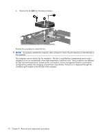
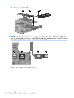
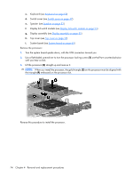
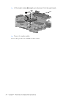
Modem module NOTE: The modem module spare part kit does not include a modem module cable. The modem module cable is included in the Cable Kit, spare part number 456594-001. Description Modem module Spare part number 441074-001 Before removing the modem module, follow these steps: 1. Shut down the computer. If you are unsure whether the computer is off or in Hibernation, turn the computer on, and then shut it down through the operating system. 2. Disconnect all external devices connected to the computer. 3. Disconnect the power from the computer by first unplugging the power cord from the AC outlet and then unplugging the AC adapter from the computer. 4. Remove the battery (see Battery on page 39). 5. Remove the following components: a. Hard drive (see Hard drive on page 40) b. Optical drive (see Optical drive on page 46) c. Keyboard (see Keyboard on page 50) d. Switch cover (see Switch cover on page 47) e. Speaker (see Speaker on page 53) f. Display lid switch module (see Display lid switch module on page 54) g. Display assembly (see Display assembly on page 55) h. Top cover (see Top cover on page 59) i. System board (see System board on page 65) Remove the modem module: 1. Turn the system board upside down, with the USB connectors toward you. 2. Remove the two Phillips PM2.5×4.0 screws (1) that secure the modem module to the system board. Component replacement procedures 75
-
 1
1 -
2
-
3
-
4
-
5
-
6
-
7
-
8
-
9
-
10
-
11
-
12
-
13
-
14
-
15
-
16
-
17
-
18
-
19
-
20
-
21
-
22
-
23
-
24
-
25
-
26
-
27
-
28
-
29
-
30
-
31
-
32
-
33
-
34
-
35
-
36
-
37
-
38
-
39
-
40
-
41
-
42
-
43
-
44
-
45
-
46
-
47
-
48
-
49
-
50
-
51
-
52
-
53
-
54
-
55
-
56
-
57
-
58
-
59
-
60
-
61
-
62
-
63
-
64
-
65
-
66
-
67
-
68
-
69
-
70
-
71
-
72
-
73
-
74
-
75
-
76
-
77
-
 78
78 -
 79
79 -
 80
80 -
 81
81 -
 82
82 -
 83
83 -
 84
84 -
 85
85 -
 86
86 -
 87
87 -
 88
88 -
89
-
90
-
91
-
92
-
93
-
94
-
95
-
96
-
97
-
98
-
99
-
100
-
101
-
102
-
103
-
104
-
105
-
106
-
107
-
108
-
109
-
110
-
111
-
112
-
113
-
114
-
115
-
116
-
117
-
118
-
119
-
120
-
121
-
122
-
123
-
124
-
125
-
126
-
127
-
128
-
129
-
130
-
131
-
132
-
133
-
134
-
135
-
136
-
137
-
138
-
139
-
140
-
141
-
142
-
143
-
144
-
145
-
146
-
147
-
148
-
149
-
150
-
151
-
152
-
153
-
154
-
155
 |
 |