HP 6820s HP Compaq 6820s Notebook PC - Maintenance and Service Guide - Page 49
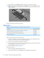
Memory module, swing it up and forward, and remove the cover. The memory
 |
UPC - 883585963447
View all HP 6820s manuals
Add to My Manuals
Save this manual to your list of manuals |
Page 49 highlights
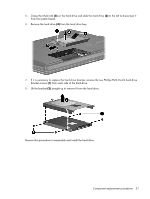
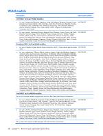
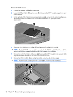
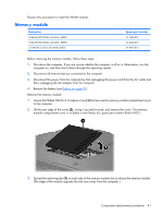
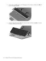
Reverse this procedure to install the WLAN module. Memory module Description 2048-MB (PC2-5300, 667-MHz, DDR2) 1024-MB (PC2-5300, 667-MHz, DDR2) 512-MB (PC2-5300, 667-MHz, DDR2) Spare part number 417506-001 414046-001 414045-001 Before removing the memory module, follow these steps: 1. Shut down the computer. If you are unsure whether the computer is off or in Hibernation, turn the computer on, and then shut it down through the operating system. 2. Disconnect all external devices connected to the computer. 3. Disconnect the power from the computer by first unplugging the power cord from the AC outlet and then unplugging the AC adapter from the computer. 4. Remove the battery (see Battery on page 35). Remove the memory module: 1. Loosen the Phillips PM2.0×5.0 captive screw (1) that secures the memory module compartment cover to the computer. 2. Lift the rear edge of the cover (2), swing it up and forward, and remove the cover. The memory module compartment cover is included in the Plastics Kit, spare part number 456614-001. 3. Spread the retaining tabs (1) on each side of the memory module slot to release the memory module. (The edge of the module opposite the slot rises away from the computer.) Component replacement procedures 41
-
 1
1 -
2
-
3
-
4
-
5
-
6
-
7
-
8
-
9
-
10
-
11
-
12
-
13
-
14
-
15
-
16
-
17
-
18
-
19
-
20
-
21
-
22
-
23
-
24
-
25
-
26
-
27
-
28
-
29
-
30
-
31
-
32
-
33
-
34
-
35
-
36
-
37
-
38
-
39
-
40
-
41
-
42
-
43
-
 44
44 -
 45
45 -
 46
46 -
 47
47 -
 48
48 -
 49
49 -
 50
50 -
 51
51 -
 52
52 -
 53
53 -
 54
54 -
55
-
56
-
57
-
58
-
59
-
60
-
61
-
62
-
63
-
64
-
65
-
66
-
67
-
68
-
69
-
70
-
71
-
72
-
73
-
74
-
75
-
76
-
77
-
78
-
79
-
80
-
81
-
82
-
83
-
84
-
85
-
86
-
87
-
88
-
89
-
90
-
91
-
92
-
93
-
94
-
95
-
96
-
97
-
98
-
99
-
100
-
101
-
102
-
103
-
104
-
105
-
106
-
107
-
108
-
109
-
110
-
111
-
112
-
113
-
114
-
115
-
116
-
117
-
118
-
119
-
120
-
121
-
122
-
123
-
124
-
125
-
126
-
127
-
128
-
129
-
130
-
131
-
132
-
133
-
134
-
135
-
136
-
137
-
138
-
139
-
140
-
141
-
142
-
143
-
144
-
145
-
146
-
147
 |
 |