HP 6820s HP Compaq 6820s Notebook PC - Maintenance and Service Guide - Page 55
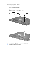
board cable, Remove the switch cover.
 |
UPC - 883585963447
View all HP 6820s manuals
Add to My Manuals
Save this manual to your list of manuals |
Page 55 highlights
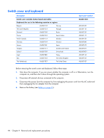
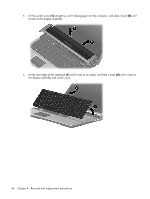
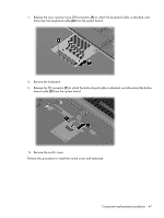
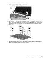
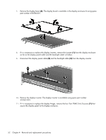
7. Release the zero insertion force (ZIF) connector (1) to which the keyboard cable is attached, and disconnect the keyboard cable (2) from the system board. 8. Remove the keyboard. 9. Release the ZIF connector (1) to which the button board cable is attached, and disconnect the button board cable (2) from the system board. 10. Remove the switch cover. Reverse this procedure to install the switch cover and keyboard. Component replacement procedures 47
-
 1
1 -
2
-
3
-
4
-
5
-
6
-
7
-
8
-
9
-
10
-
11
-
12
-
13
-
14
-
15
-
16
-
17
-
18
-
19
-
20
-
21
-
22
-
23
-
24
-
25
-
26
-
27
-
28
-
29
-
30
-
31
-
32
-
33
-
34
-
35
-
36
-
37
-
38
-
39
-
40
-
41
-
42
-
43
-
44
-
45
-
46
-
47
-
48
-
49
-
 50
50 -
 51
51 -
 52
52 -
 53
53 -
 54
54 -
 55
55 -
 56
56 -
 57
57 -
 58
58 -
 59
59 -
 60
60 -
61
-
62
-
63
-
64
-
65
-
66
-
67
-
68
-
69
-
70
-
71
-
72
-
73
-
74
-
75
-
76
-
77
-
78
-
79
-
80
-
81
-
82
-
83
-
84
-
85
-
86
-
87
-
88
-
89
-
90
-
91
-
92
-
93
-
94
-
95
-
96
-
97
-
98
-
99
-
100
-
101
-
102
-
103
-
104
-
105
-
106
-
107
-
108
-
109
-
110
-
111
-
112
-
113
-
114
-
115
-
116
-
117
-
118
-
119
-
120
-
121
-
122
-
123
-
124
-
125
-
126
-
127
-
128
-
129
-
130
-
131
-
132
-
133
-
134
-
135
-
136
-
137
-
138
-
139
-
140
-
141
-
142
-
143
-
144
-
145
-
146
-
147
 |
 |
7
.
Release the zero insertion force (ZIF) connector
(1)
to which the keyboard cable is attached, and
disconnect the keyboard cable
(2)
from the system board.
8
.
Remove the keyboard.
9
.
Release the ZIF connector
(1)
to which the button board cable is attached, and disconnect the button
board cable
(2)
from the system board.
10
.
Remove the switch cover.
Reverse this procedure to install the switch cover and keyboard.
Component replacement procedures
47