HP 6820s HP Compaq 6820s Notebook PC - Maintenance and Service Guide - Page 70
Lift the rear edge of the system board, is clear of
 |
UPC - 883585963447
View all HP 6820s manuals
Add to My Manuals
Save this manual to your list of manuals |
Page 70 highlights
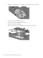
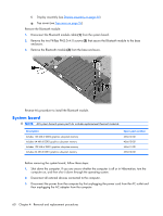
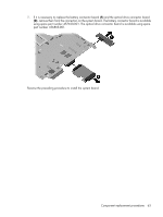
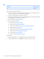
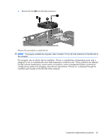
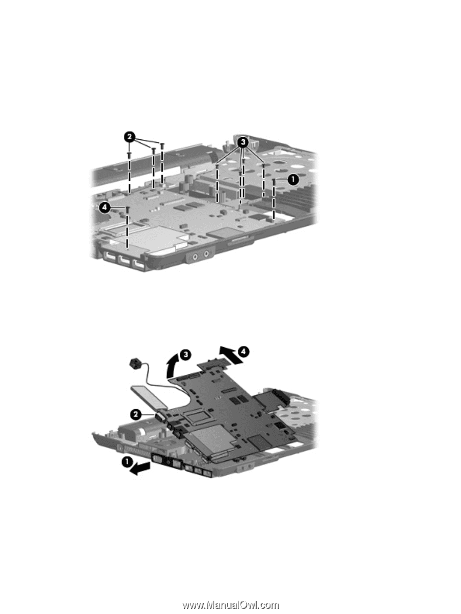
3. Remove the following screws: (1) One Torx T8M2.5×6.0 screw that secures the system board to the base enclosure (2) Three Torx T8M2.5×6.0 screws that secure the battery connector board to the base enclosure (3) Four Torx T8M2.5×4.0 screws that secure the optical drive connector board to the base enclosure (4) One Phillips PMM2.0×6.0 screw that secures the system board to the base enclosure 4. Flex the left side of the base enclosure (1) until the external monitor connector (2) is clear of the opening in the base enclosure. 5. Lift the rear edge of the system board (3) until it rests at an angle. 6. Remove the system board (4) from the base enclosure by sliding it back. 62 Chapter 4 Removal and replacement procedures
-
 1
1 -
2
-
3
-
4
-
5
-
6
-
7
-
8
-
9
-
10
-
11
-
12
-
13
-
14
-
15
-
16
-
17
-
18
-
19
-
20
-
21
-
22
-
23
-
24
-
25
-
26
-
27
-
28
-
29
-
30
-
31
-
32
-
33
-
34
-
35
-
36
-
37
-
38
-
39
-
40
-
41
-
42
-
43
-
44
-
45
-
46
-
47
-
48
-
49
-
50
-
51
-
52
-
53
-
54
-
55
-
56
-
57
-
58
-
59
-
60
-
61
-
62
-
63
-
64
-
 65
65 -
 66
66 -
 67
67 -
 68
68 -
 69
69 -
 70
70 -
 71
71 -
 72
72 -
 73
73 -
 74
74 -
 75
75 -
76
-
77
-
78
-
79
-
80
-
81
-
82
-
83
-
84
-
85
-
86
-
87
-
88
-
89
-
90
-
91
-
92
-
93
-
94
-
95
-
96
-
97
-
98
-
99
-
100
-
101
-
102
-
103
-
104
-
105
-
106
-
107
-
108
-
109
-
110
-
111
-
112
-
113
-
114
-
115
-
116
-
117
-
118
-
119
-
120
-
121
-
122
-
123
-
124
-
125
-
126
-
127
-
128
-
129
-
130
-
131
-
132
-
133
-
134
-
135
-
136
-
137
-
138
-
139
-
140
-
141
-
142
-
143
-
144
-
145
-
146
-
147
 |
 |
3
.
Remove the following screws:
(1)
One Torx T8M2.5×6.0 screw that secures the system board to the base enclosure
(2)
Three Torx T8M2.5×6.0 screws that secure the battery connector board to the base enclosure
(3)
Four Torx T8M2.5×4.0 screws that secure the optical drive connector board to the base enclosure
(4)
One Phillips PMM2.0×6.0 screw that secures the system board to the base enclosure
4
.
Flex the left side of the base enclosure
(1)
until the external monitor connector
(2)
is clear of the
opening in the base enclosure.
5
.
Lift the rear edge of the system board
(3)
until it rests at an angle.
6
.
Remove the system board
(4)
from the base enclosure by sliding it back.
62
Chapter
4
Removal and replacement procedures