HP 6820s HP Compaq 6820s Notebook PC - Maintenance and Service Guide - Page 77
until you hear a click., Lift the processor
 |
UPC - 883585963447
View all HP 6820s manuals
Add to My Manuals
Save this manual to your list of manuals |
Page 77 highlights
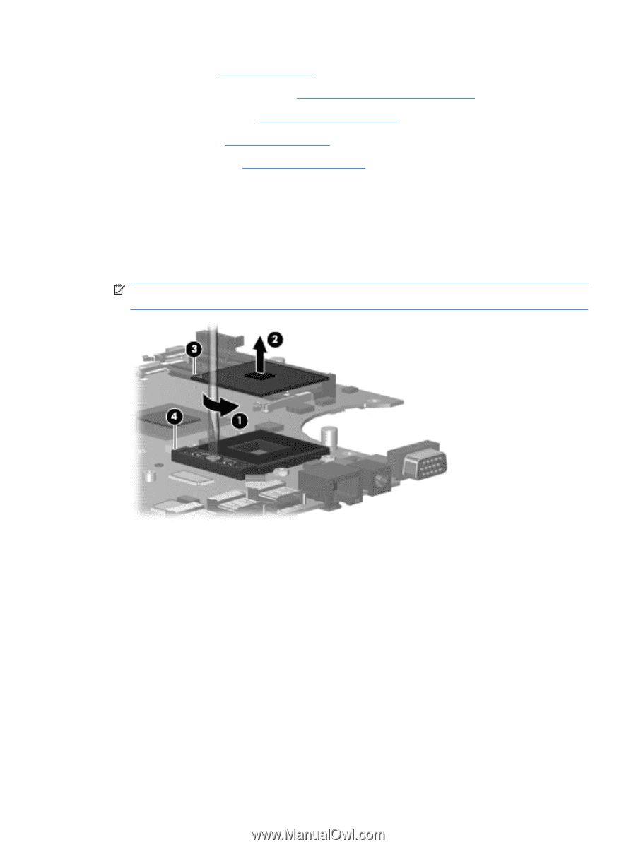
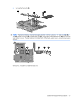
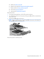
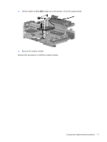
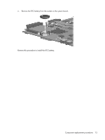
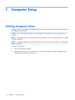
d. Speaker (see Speaker on page 48) e. Display lid switch module (see Display lid switch module on page 49) f. Display assembly (see Display assembly on page 50) g. Top cover (see Top cover on page 54) h. System board (see System board on page 60) Remove the processor: 1. Turn the system board upside down, with the USB connectors toward you. 2. Use a flat-bladed screwdriver to turn the processor locking screw (1) one-half turn counterclockwise until you hear a click. 3. Lift the processor (2) straight up and remove it. NOTE: When you install the processor, the gold triangle (3) on the processor must be aligned with the triangle (4) embossed on the processor slot. Reverse this procedure to install the processor. Component replacement procedures 69
-
 1
1 -
2
-
3
-
4
-
5
-
6
-
7
-
8
-
9
-
10
-
11
-
12
-
13
-
14
-
15
-
16
-
17
-
18
-
19
-
20
-
21
-
22
-
23
-
24
-
25
-
26
-
27
-
28
-
29
-
30
-
31
-
32
-
33
-
34
-
35
-
36
-
37
-
38
-
39
-
40
-
41
-
42
-
43
-
44
-
45
-
46
-
47
-
48
-
49
-
50
-
51
-
52
-
53
-
54
-
55
-
56
-
57
-
58
-
59
-
60
-
61
-
62
-
63
-
64
-
65
-
66
-
67
-
68
-
69
-
70
-
71
-
 72
72 -
 73
73 -
 74
74 -
 75
75 -
 76
76 -
 77
77 -
 78
78 -
 79
79 -
 80
80 -
 81
81 -
 82
82 -
83
-
84
-
85
-
86
-
87
-
88
-
89
-
90
-
91
-
92
-
93
-
94
-
95
-
96
-
97
-
98
-
99
-
100
-
101
-
102
-
103
-
104
-
105
-
106
-
107
-
108
-
109
-
110
-
111
-
112
-
113
-
114
-
115
-
116
-
117
-
118
-
119
-
120
-
121
-
122
-
123
-
124
-
125
-
126
-
127
-
128
-
129
-
130
-
131
-
132
-
133
-
134
-
135
-
136
-
137
-
138
-
139
-
140
-
141
-
142
-
143
-
144
-
145
-
146
-
147
 |
 |