HP 6820s HP Compaq 6820s Notebook PC - Maintenance and Service Guide - Page 69
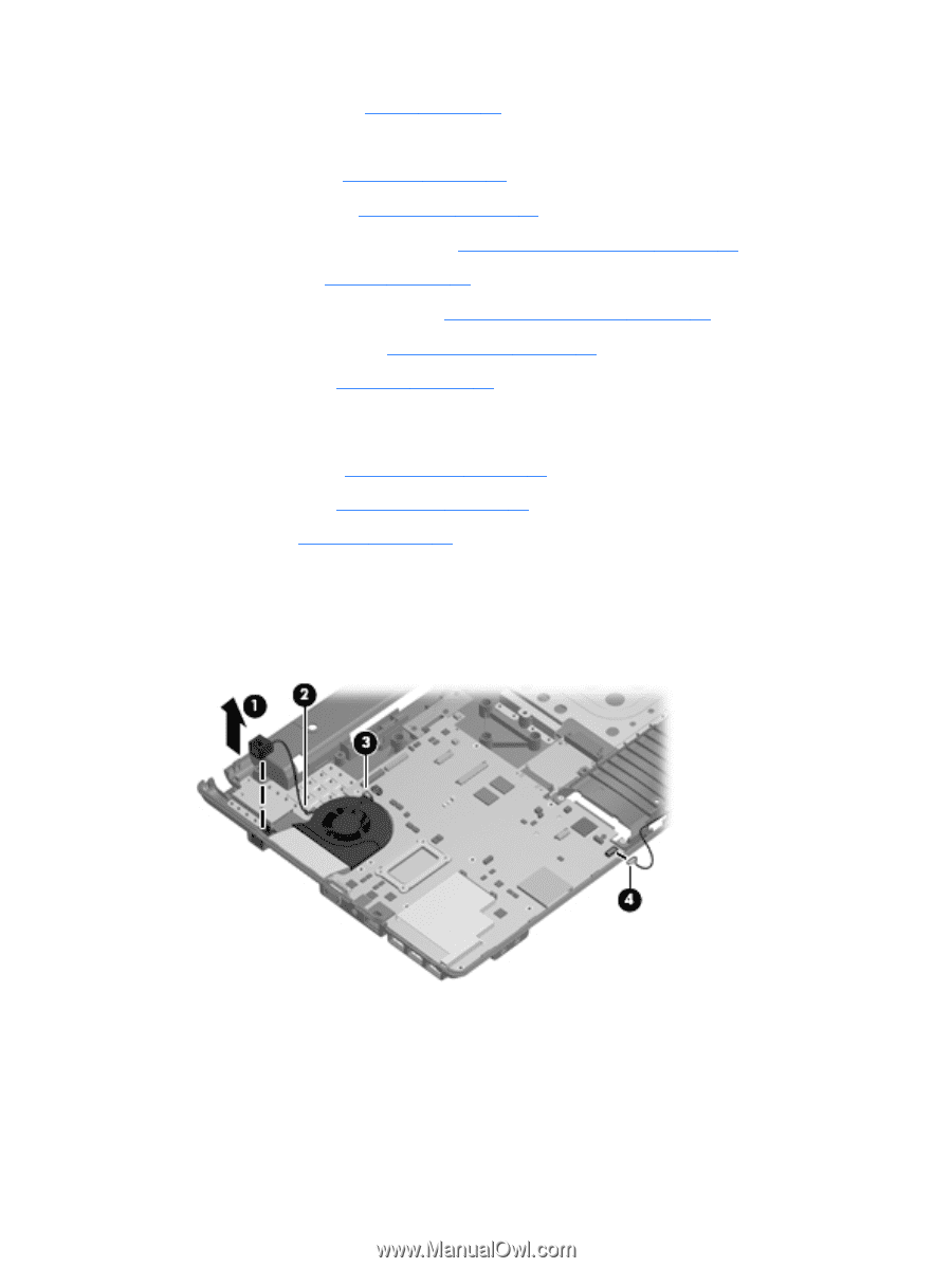
Remove the RJ-11 jack, Remove the system board
 |
UPC - 883585963447
View all HP 6820s manuals
Add to My Manuals
Save this manual to your list of manuals |
Page 69 highlights
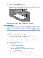
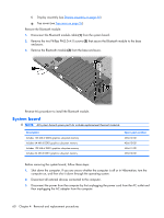
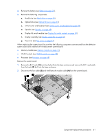
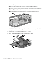
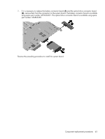
4. Remove the battery (see Battery on page 35). 5. Remove the following components: a. Hard drive (see Hard drive on page 36) b. Optical drive (see Optical drive on page 42) c. Switch cover and keyboard (see Switch cover and keyboard on page 44) d. Speaker (see Speaker on page 48) e. Display lid switch module (see Display lid switch module on page 49) f. Display assembly (see Display assembly on page 50) g. Top cover (see Top cover on page 54) When replacing the system board, be sure that the following components are removed from the defective system board and installed on the replacement system board: ● Memory module (see Memory module on page 41) ● WLAN module (see WLAN module on page 38) ● Processor (see Processor on page 68) Remove the system board: 1. Remove the RJ-11 jack (1) from the clip built into the base enclosure and remove the RJ-11 jack cable from the hook (2) built into the base enclosure. 2. Disconnect the fan cable (3) and the Bluetooth module cable (4) from the system board. Component replacement procedures 61
-
 1
1 -
2
-
3
-
4
-
5
-
6
-
7
-
8
-
9
-
10
-
11
-
12
-
13
-
14
-
15
-
16
-
17
-
18
-
19
-
20
-
21
-
22
-
23
-
24
-
25
-
26
-
27
-
28
-
29
-
30
-
31
-
32
-
33
-
34
-
35
-
36
-
37
-
38
-
39
-
40
-
41
-
42
-
43
-
44
-
45
-
46
-
47
-
48
-
49
-
50
-
51
-
52
-
53
-
54
-
55
-
56
-
57
-
58
-
59
-
60
-
61
-
62
-
63
-
 64
64 -
 65
65 -
 66
66 -
 67
67 -
 68
68 -
 69
69 -
 70
70 -
 71
71 -
 72
72 -
 73
73 -
 74
74 -
75
-
76
-
77
-
78
-
79
-
80
-
81
-
82
-
83
-
84
-
85
-
86
-
87
-
88
-
89
-
90
-
91
-
92
-
93
-
94
-
95
-
96
-
97
-
98
-
99
-
100
-
101
-
102
-
103
-
104
-
105
-
106
-
107
-
108
-
109
-
110
-
111
-
112
-
113
-
114
-
115
-
116
-
117
-
118
-
119
-
120
-
121
-
122
-
123
-
124
-
125
-
126
-
127
-
128
-
129
-
130
-
131
-
132
-
133
-
134
-
135
-
136
-
137
-
138
-
139
-
140
-
141
-
142
-
143
-
144
-
145
-
146
-
147
 |
 |