HP 8/20q HP StorageWorks 8/20q Fibre Channel Switch installation and reference - Page 29
Mount the switch
 |
View all HP 8/20q manuals
Add to My Manuals
Save this manual to your list of manuals |
Page 29 highlights
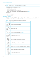
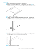
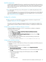
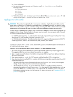
Installing a 8/20q Fibre Channel Switch involves the following steps: 1. Mount the switch, page 29 2. Install the transceivers, page 33 3. Configure the workstation, page 33 4. Apply power to the switch, page 34 5. Connect the management station or workstation to the switch, page 35 6. Configure the switch, page 35 7. Cable devices to the switch, page 36 Mount the switch The switch can be placed on a flat surface and stacked, or mounted in a 19" Electronics Industries Association (EIA) rack. See "Weight and physical dimensions" on page 57 for weight and dimensional specifications. Adhesive rubber feet are provided for surface mounts only. Without the rubber feet, the switch occupies 1U of space in an EIA rack. The rack mount kit is supported with the following HP custom racks only: • HP 9000 Series Rack • HP 10000 Series Rack • HP 10000 G2 Series Rack Before you begin WARNING! To reduce the risk of personal injury or damage to the equipment, ensure that: • In single-rack installations, stabilizing feet are attached to the rack. • In multiple-rack installations, racks are coupled together. • Leveling jacks on the rack are extended to the floor. • The full weight of the rack rests on the leveling jacks. • Heavy items, such as uninterruptible power supplies and hard drive storage enclosures, are installed near the bottom of the rack. • Similar components are installed next to each other in the rack. Because devices are of differing depths, this will facilitate maintenance and service tasks. • Only one device in a rack is extended at a time. A rack may become unstable if more than one device is extended. CAUTION: • For proper airflow, the SFP+ media side (port side) of the device must face the front of the rack. Mounting the switch in this direction allows air to enter from the front of the rack (SFP-port side of switch) and exhaust through the back of the rack (power-supply side of switch). This prevents overheating, which may cause equipment in the rack to fail. • Allow a minimum of 63.5 cm (25 in.) clearance in front of the rack to allow the doors to open fully, and 76.2 cm (30 in.) in back of the rack to allow for servicing and airflow. • If the device is mounted in a closed rack or there are multiple rack-mounted devices, make sure that the operating temperature inside the rack enclosure does not exceed the maximum rated ambient temperature. • Multiple rack-mounted devices connected to the same AC supply circuit may overload that circuit or the AC supply wiring. Consider the power source capacity and the total power usage of all switches on the circuit. • Reliable grounding in the rack must be maintained. 8/20q Fibre Channel Switch installation and reference guide 29
-
 1
1 -
2
-
3
-
4
-
5
-
6
-
7
-
8
-
9
-
10
-
11
-
12
-
13
-
14
-
15
-
16
-
17
-
18
-
19
-
20
-
21
-
22
-
23
-
 24
24 -
 25
25 -
 26
26 -
 27
27 -
 28
28 -
 29
29 -
 30
30 -
 31
31 -
 32
32 -
 33
33 -
 34
34 -
35
-
36
-
37
-
38
-
39
-
40
-
41
-
42
-
43
-
44
-
45
-
46
-
47
-
48
-
49
-
50
-
51
-
52
-
53
-
54
-
55
-
56
-
57
-
58
-
59
-
60
-
61
-
62
-
63
-
64
-
65
-
66
-
67
-
68
-
69
-
70
-
71
-
72
 |
 |
