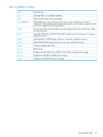
HP BladeSystem c3000 HP BladeSystem Deployment Guide for Solutions with 6Gb SA - Page 58
enclosure to the SAS switch. Connect the MSA 2040 MSA or P2000 G3 SAS MSA
 |
View all HP BladeSystem c3000 manuals
Add to My Manuals
Save this manual to your list of manuals |
Page 58 highlights
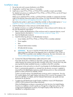
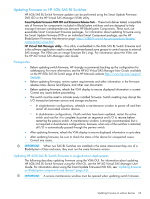
g. Connect the Ethernet cables and power cords. h. Apply power to the storage enclosures: • Power on any cascaded drive enclosures and allow them to complete its POST. Make sure that the drive enclosures complete their startup routines before powering on the controller enclosure. If the controller enclosure is powered on prematurely, it may not properly discover the attached storage. • Power on the controller enclosure and allow it to complete POST. • Confirm successful startup of the MSA enclosures and their hard drives. View the LEDs on the front and rear of each MSA to monitor the progress of the POST. For more information about MSA LED patterns, see "LED descriptions" in the HP MSA 2040 User Guide or the HP P2000 G3 SAS MSA User Guide. i. If needed, upgrade the firmware on the MSA 2040 SAS or P2000 G3 SAS MSA controllers, using the firmware and instructions obtained in Step 7.c. For more information about updating firmware on the P2000 G3 SAS MSA, see "Updating firmware on shared SAS storage (MSA 2040 SAS or P2000 G3 SAS MSA controller enclosures and its cascaded MSA 2040, P2000, MSA2000, and D2700 drive enclosures)" (page 67) j. Install required MSA-specific drivers and software, such as the multipathing Device Specific Module, on each server that will access the MSA 2040 SAS or P2000 G3 SAS MSA. For information, see "Host System Requirements" in the MSA 2040 User Guide, the HP P2000 G3 MSA System SAS User Guide, and the MSA 2040 SAS or P2000 G3 MSA Systems QuickSpecs. k. Connect SAS cables from the MSA 2040 MSA or P2000 G3 SAS MSA controller enclosure to the SAS switch. Connect the MSA 2040 MSA or P2000 G3 SAS MSA controller enclosure to the SAS switch only after upgrading the controller firmware to the latest version. Be sure to follow provided guidelines of a fault-tolerant cabling configuration to provide a highly available solution. For more information about cabling storage enclosures to the switch, see "Deployment examples" (page 71). 8. Install the MDS600 or D6000 storage enclosures. If not included in your solution, proceed to the next step. For detailed instructions on installing MDS600 or D6000 storage enclosures, see "Setup" in the HP 600 Modular Disk System User Guide. or HP D6000 Disk Enclosure User Guide a. Before installing each MDS600 or D6000 storage enclosure, record important device information in "MDS600 and D6000 storage enclosure worksheet" (page 106). b. Determine the currently-installed firmware version and record it in the provided spaces in "MDS600 and D6000 storage enclosure worksheet" (page 106). Firmware version information is displayed in the VSM. In the Systems and Devices navigation tree, select the MDS600 or D6000, and then click More Information. c. Determine if there is a newer version of firmware available. Firmware for the MDS600 or D6000 can be obtained from the HP Support Downloads website (http://www.hp.com/ support/downloads. Be sure to download and use the .fuf file download; do not download the Smart Component .scexe file, because it is not supported in this solution environment.) d. Rack the MDS600 or D6000 storage enclosure. e. Insert drives in the MDS600 or D6000 storage enclosure drawers. Be sure that either a blank module or a drive is installed in each drive bay, to ensure proper airflow and cooling. f. Connect SAS cables from the MDS600 or D6000 I/O modules to the switch. Be sure to follow provided guidelines of a fault-tolerant cabling configuration to utilize the high-availability features. 58 Installation best practices and procedures
-
 1
1 -
2
-
3
-
4
-
5
-
6
-
7
-
8
-
9
-
10
-
11
-
12
-
13
-
14
-
15
-
16
-
17
-
18
-
19
-
20
-
21
-
22
-
23
-
24
-
25
-
26
-
27
-
28
-
29
-
30
-
31
-
32
-
33
-
34
-
35
-
36
-
37
-
38
-
39
-
40
-
41
-
42
-
43
-
44
-
45
-
46
-
47
-
48
-
49
-
50
-
51
-
52
-
 53
53 -
 54
54 -
 55
55 -
 56
56 -
 57
57 -
 58
58 -
 59
59 -
 60
60 -
 61
61 -
 62
62 -
 63
63 -
64
-
65
-
66
-
67
-
68
-
69
-
70
-
71
-
72
-
73
-
74
-
75
-
76
-
77
-
78
-
79
-
80
-
81
-
82
-
83
-
84
-
85
-
86
-
87
-
88
-
89
-
90
-
91
-
92
-
93
-
94
-
95
-
96
-
97
-
98
-
99
-
100
-
101
-
102
-
103
-
104
-
105
-
106
-
107
-
108
-
109
-
110
-
111
 |
 |