HP Brio ba300 hp brio ba300, technical reference manual (product description) - Page 26
BIOS addresses
 |
View all HP Brio ba300 manuals
Add to My Manuals
Save this manual to your list of manuals |
Page 26 highlights
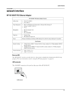
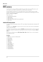
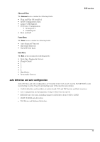
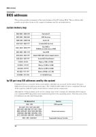
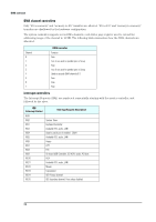
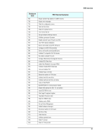
BIOS overview BIOS addresses This section provides a summary of the main features of the HP system BIOS. This is software that provides an interface between the computer hardware and the operating system. system memory map 0000 0000 - 0000 03FF 0000 0400 - 0000 04FF 0000 0500 - 0009 FC00 0009 FC00 - 0009 FFFF 000A_0000 - 000B_FFFF 000C 0000 - 000C 7FFF 000C 8000 - 000F FFFF 000E 0000 - 000F FFFF 10 0000 - FF FFFF 100 0000 - 1FF FFFF 200 0000 -3FF FFFF 400 0000 -1FFF FFFF FFF80000 - FFFF FFFF Real-mode IDT BIOS Data Area Used by OS Extended BIOS Data Area Video RAM or SMRAM (not visible unless in SMM) Video ROM Adapter ROM, RAM, memory-mapped registers System BIOS (Flash/Shadow) Memory (1 MB to 16 MB) Memory (16 MB to 32 MB) Memory (32 MB to 64 MB) Memory (64 MB to 512 MB) 512 KB BIOS (Flash) hp I/O port map (I/O addresses used by the system) Peripheral devices, accessory devices and system controllers are accessed via the system I/O space, which is not located in system memory space. The 64 KB of addressable I/O space comprises 8-bit and 16-bit registers (called I/O ports) located in the various system components. Although the Setup program can be used to change some of the settings, the following address map is not completely BIOS dependent, but is determined partly by the operating system. Note that some of the I/O addresses are allocated dynamically. I/O Address Ports 0000 - 000F 0010-001F, 0022 -003F, 0044-005F, 0062-0063, 0065-006F, 0072-007F, 00840086, 04D0-04D1, 0080, 0088, 008C-008E, 0090-009F, 00A2-00BF, 00E0-00EF, 0400047F, 0480-04BF, 04D0-04D1, 0800-0847F 0020 - 0021, 00A0-00A1 Function DMA controller System board resources Programmable Interrupt Controller 26
-
 1
1 -
2
-
3
-
4
-
5
-
6
-
7
-
8
-
9
-
10
-
11
-
12
-
13
-
14
-
15
-
16
-
17
-
18
-
19
-
20
-
 21
21 -
 22
22 -
 23
23 -
 24
24 -
 25
25 -
 26
26 -
 27
27 -
 28
28 -
 29
29 -
 30
30 -
 31
31 -
32
-
33
-
34
-
35
-
36
-
37
-
38
 |
 |
