HP Chromebook 11-2100 Maintenance and Service Guide - Page 41
Connector board, Release the ZIF connector
 |
View all HP Chromebook 11-2100 manuals
Add to My Manuals
Save this manual to your list of manuals |
Page 41 highlights
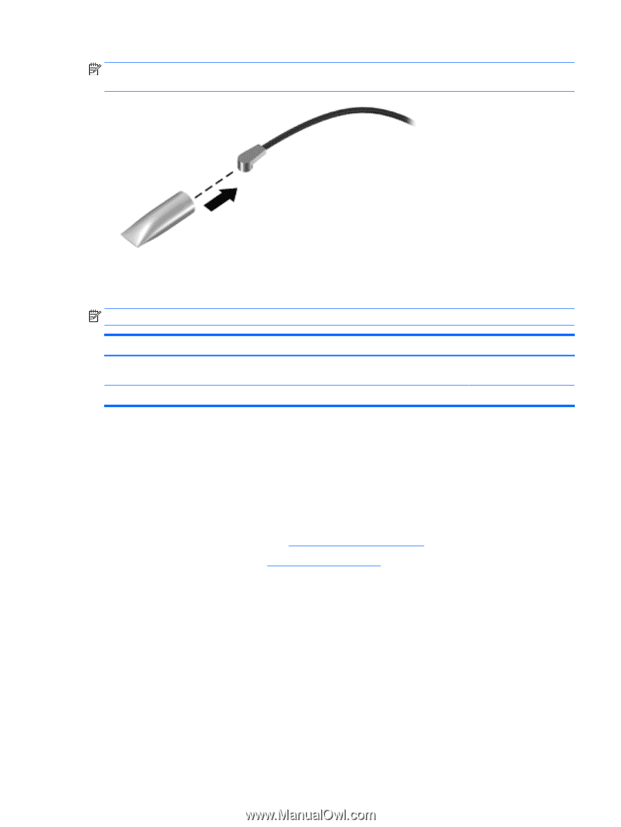
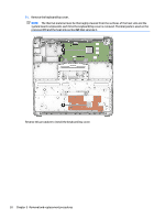
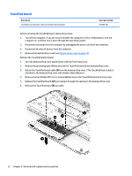
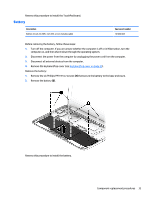
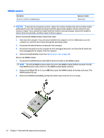
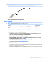
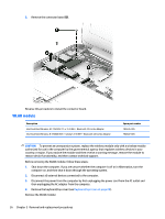
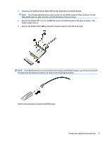
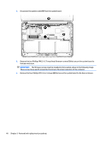
NOTE: If the WWAN antenna is not connected to the terminal on the WWAN module, a protective sleeve must be installed on the antenna connector, as shown in the following illustration. Reverse this procedure to install the WWAN module. Connector board NOTE: The connector board spare part kit includes the cable. Description For use only on computer models equipped with WWAN capability (includes SD Card Reader slot and SIM slot) For use only on computer models not equipped with WWAN capability (includes SD Card Reader slot) Spare part number 785884-001 783087-001 Before removing the connector board, follow these steps: 1. Shut down the computer. If you are unsure whether the computer is off or in Hibernation, turn the computer on, and then shut it down through the operating system. 2. Disconnect all external devices connected to the computer. 3. Disconnect the power from the computer by first unplugging the power cord from the AC outlet and then unplugging the AC adapter from the computer. 4. Remove the keyboard/top cover (see Keyboard/top cover on page 25). 5. Remove the WWAN module (see WWAN module on page 34). Remove the connector board: 1. Release the ZIF connector (1) to which the connector board cable is attached, and then disconnect the connector board cable from the system board. 2. Remove the two Philllips PM1.9×4.2 screws (2) that secure the connector board to the base enclosure. Component replacement procedures 35
-
 1
1 -
2
-
3
-
4
-
5
-
6
-
7
-
8
-
9
-
10
-
11
-
12
-
13
-
14
-
15
-
16
-
17
-
18
-
19
-
20
-
21
-
22
-
23
-
24
-
25
-
26
-
27
-
28
-
29
-
30
-
31
-
32
-
33
-
34
-
35
-
 36
36 -
 37
37 -
 38
38 -
 39
39 -
 40
40 -
 41
41 -
 42
42 -
 43
43 -
 44
44 -
 45
45 -
 46
46 -
47
-
48
-
49
-
50
-
51
-
52
-
53
-
54
-
55
-
56
-
57
-
58
-
59
-
60
-
61
-
62
-
63
-
64
-
65
-
66
-
67
-
68
-
69
-
70
 |
 |