HP Chromebook 11-2100 Maintenance and Service Guide - Page 45
System board
 |
View all HP Chromebook 11-2100 manuals
Add to My Manuals
Save this manual to your list of manuals |
Page 45 highlights
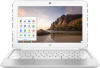
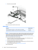
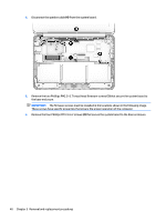
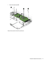
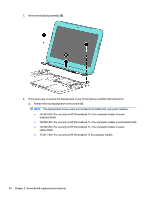
System board NOTE: The system board spare part kit includes 16-GB of eMMC primary storage and replacement thermal material. Description Equipped with an Intel Celeron N2840 2.16-GHz (SC turbo up to 2.58-GHz) dual core processor (1.0-GB L2 cache, 1333-MHz FSB, 4.5 W) and 4.0-GB of system memory Equipped with an Intel Celeron N2840 2.16-GHz (SC turbo up to 2.58-GHz) dual core processor (1.0-GB L2 cache, 1333-MHz FSB, 4.5 W) and 2.0-GB of system memory Equipped with an Intel Celeron N2830 2.16-GHz (SC turbo up to 2.41-GHz) dual core processor (1.0-GB L2 cache, 1333-MHz FSB, 4.5 W) and 4.0-GB of system memory Equipped with an Intel Celeron N2830 2.16-GHz (SC turbo up to 2.41-GHz) dual core processor (1.0-GB L2 cache, 1333-MHz FSB, 4.5 W) and 2.0-GB of system memory Spare part number 790940-001 790939-001 783074-001 783073-001 Before removing the system board, follow these steps: 1. Turn off the computer. If you are unsure whether the computer is off or in Hibernation, turn the computer on, and then shut it down through the operating system. 2. Disconnect the power from the computer by unplugging the power cord from the computer. 3. Disconnect all external devices from the computer. 4. Remove the keyboard/top cover (see Keyboard/top cover on page 25). 5. Remove the WWAN module (see WWAN module on page 34). 6. Remove the WLAN module (see WLAN module on page 36). Remove the system board: 1. Release the ZIF connector (1) to which the connector board cable is attached, and then disconnect the connector board cable from the system board. 2. Disconnect the power connector cable (2) from the system board. 3. Release the ZIF connector (3) to which the display panel cable is attached, and then disconnect the display panel cable from the system board. Component replacement procedures 39
-
 1
1 -
2
-
3
-
4
-
5
-
6
-
7
-
8
-
9
-
10
-
11
-
12
-
13
-
14
-
15
-
16
-
17
-
18
-
19
-
20
-
21
-
22
-
23
-
24
-
25
-
26
-
27
-
28
-
29
-
30
-
31
-
32
-
33
-
34
-
35
-
36
-
37
-
38
-
39
-
 40
40 -
 41
41 -
 42
42 -
 43
43 -
 44
44 -
 45
45 -
 46
46 -
 47
47 -
 48
48 -
 49
49 -
 50
50 -
51
-
52
-
53
-
54
-
55
-
56
-
57
-
58
-
59
-
60
-
61
-
62
-
63
-
64
-
65
-
66
-
67
-
68
-
69
-
70
 |
 |