HP Chromebook 11-2100 Maintenance and Service Guide - Page 49
Display assembly, to which the display panel cable is attached, and then disconnect
 |
View all HP Chromebook 11-2100 manuals
Add to My Manuals
Save this manual to your list of manuals |
Page 49 highlights
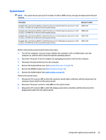
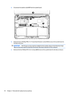
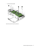
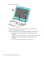
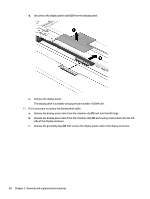
Display assembly NOTE: The display assembly is spared at the subcomponent level only. For more display assembly spare part information, see the individual removal subsections. Before removing the display assembly, follow these steps: 1. Turn off the computer. If you are unsure whether the computer is off or in Hibernation, turn the computer on, and then shut it down through the operating system. 2. Disconnect the power from the computer by unplugging the power cord from the computer. 3. Disconnect all external devices from the computer. 4. Remove the keyboard/top cover (see Keyboard/top cover on page 25). Remove the display assembly: 1. Disconnect the WWAN antenna cables (1) from the terminals on the WWAN module. NOTE: The #5/red WWAN antenna cable connects to the WWAN module #5/Main terminal. The #6/ blue WWAN antenna cable connects to the WWAN module #6/Aux terminal. 2. Disconnect the WLAN antenna cables (2) from the terminals on the WLAN module. NOTE: The #1/white WLAN antenna cable connects to the WLAN module #1/Main terminal. The #2/ black WLAN antenna cable connects to the WLAN module #2/Aux terminal. 3. Release the ZIF connector (3) to which the display panel cable is attached, and then disconnect the display panel cable from the system board. 4. Release the display panel cable from the routing clips (4) and channel built into the base enclosure. 5. Release the WLAN antenna cables from the routing clips (5) and channel built into the base enclosure. 6. Remove the two Phillips PM2.4×5.7 screws (1) that secure the display assembly to the base enclosure. Component replacement procedures 43
-
 1
1 -
2
-
3
-
4
-
5
-
6
-
7
-
8
-
9
-
10
-
11
-
12
-
13
-
14
-
15
-
16
-
17
-
18
-
19
-
20
-
21
-
22
-
23
-
24
-
25
-
26
-
27
-
28
-
29
-
30
-
31
-
32
-
33
-
34
-
35
-
36
-
37
-
38
-
39
-
40
-
41
-
42
-
43
-
 44
44 -
 45
45 -
 46
46 -
 47
47 -
 48
48 -
 49
49 -
 50
50 -
 51
51 -
 52
52 -
 53
53 -
 54
54 -
55
-
56
-
57
-
58
-
59
-
60
-
61
-
62
-
63
-
64
-
65
-
66
-
67
-
68
-
69
-
70
 |
 |