HP Cluster Platform Hardware Kits v2010 ProCurve 1U Rack Mount Bracket Install - Page 7
Installing and Using the ProCurve 1U Rack Mount Brackets
 |
View all HP Cluster Platform Hardware Kits v2010 manuals
Add to My Manuals
Save this manual to your list of manuals |
Page 7 highlights
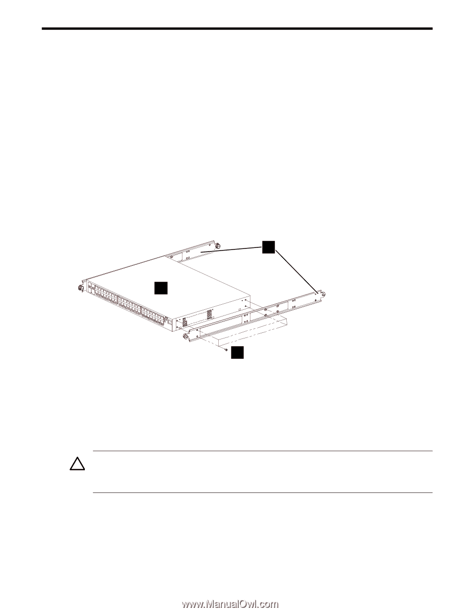
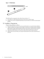
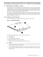
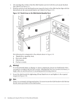
2 Installing and Using the ProCurve 1U Rack Mount Brackets 2.1 Identifying the Installation Location The installation location is dependent on the configuration rules for your XC Cluster upgrade bundle. See Section 1.2 for information on where you can obtain XC documentation resources. An upgrade bundle consists of a number of different components, such as ProLiant DL380 servers, ProCurve switches, and cables of predetermined length. Each component occupies a specific rack location so that the inter-component cabling is correct. The ProCurve 1U Rack Mount Bracket kit occupies 1U (1.75 inches) of space in the rack. Each 1U rack location is numbered 01-42 from the bottom to the top of the rack columns. There are three mounting holes for each 1U of space in the rack. For ease of reference, mark the column positions with tape or a marker pen. 2.2 Installing the Slide Brackets Section 2.2 describes how to install the slide brackets on the ProCurve switch. Figure 2-1 Attach the Slide Brackets 2 1 3 The following list corresponds to the callouts shown in Figure 2-1. 1. ProCurve Switch 2. Slide brackets 3. M4 x 8 mm Phillips (Posidrive) Attach the slide brackets to the switch as follows: 1. Identify the four screw hole locations, as shown in Figure 2-1. Caution: Use only the specified screws. Screws that are too long might penetrate the switch chassis and cause damage to internal components. 2. Use a #2 Phillips (Posidrive) screwdriver to secure the slide bracket to the switch chassis with four M4 x 8 mm Phillips (Posidrive) screws. Tighten all the M4 x 8 mm screws to the required torque. 2.1 Identifying the Installation Location 7
-
 1
1 -
 2
2 -
 3
3 -
 4
4 -
 5
5 -
 6
6 -
 7
7 -
 8
8 -
 9
9 -
 10
10 -
 11
11 -
 12
12 -
13
-
14
 |
 |