HP Cluster Platform Hardware Kits v2010 ProCurve 1U Rack Mount Bracket Install - Page 9
Alignment Washer, Caution, Inserting the ProCurve Switch in the Rack
 |
View all HP Cluster Platform Hardware Kits v2010 manuals
Add to My Manuals
Save this manual to your list of manuals |
Page 9 highlights
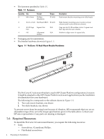
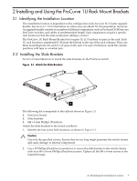
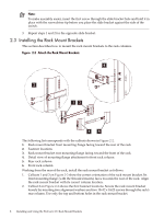
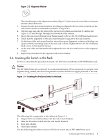
Figure 2-3 Alignment Washer The raised bumps on the alignment washers (Figure 2-3) face inward, toward the rack mount bracket's threaded insert. 3. Ensure that the rack mount bracket's rear flange is aligned with the correct location on the rack's front column as indicated by callout 3 in Figure 2-2. 4. Clip the cage nuts into the holes in the rack's front column as indicated by callout 4 in Figure 2-2. Push the clips through from the back of the column. 5. Secure the rack mount bracket's rear flange loosely with two 10-32 x 0.625 pan head screws. 6. Check that the alignment of the rack mount bracket is square to the rack columns. 7. At the front of the rack mount bracket, rotate the square alignment washers so that they are square with the mounting holes in the rear rack column. Tighten the two 10-32 x 0.625 pan head screws to the required torque. 8. At the rear of the rack mount bracket, tighten the two 10-32 x 0.625 screws to the required torque. 9. Repeat the procedure for the opposite rack mount bracket. 2.4 Inserting the Switch in the Rack Section 2.4 describes the procedure to insert a 1U ProCurve switch into an HP 10000 Series rack. Caution: The HP 10000 Series 42U rack is tall. To avoid potential injury, HP recommends two people work together using a stable, elevated work platform to lift the switch into upper positions in the rack. Figure 2-4 Inserting the ProCurve Switch in the Rack 4 3 1 2 The following list corresponds to the callouts in Figure 2-4. 1. Align switch and slide brackets with the rack mount brackets 2. Slide the ProCurve switch into the rack mount brackets 3. Rear rack column 4. Front rack column Use the following procedure to insert a ProCurve switch into an HP 10000 Series rack: 2.4 Inserting the Switch in the Rack 9
-
 1
1 -
2
-
3
-
 4
4 -
 5
5 -
 6
6 -
 7
7 -
 8
8 -
 9
9 -
 10
10 -
 11
11 -
 12
12 -
 13
13 -
 14
14
 |
 |
