HP Dc5850 Hardware Reference Guide - dc5850 Microtower Models - Page 34
Installing an External 5.25-inch or 3.5-inch Drive, Installing Guide Screws Optical Drive Shown
 |
UPC - 884962022993
View all HP Dc5850 manuals
Add to My Manuals
Save this manual to your list of manuals |
Page 34 highlights
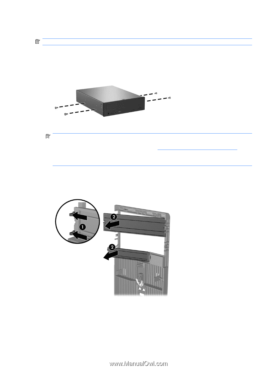
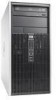
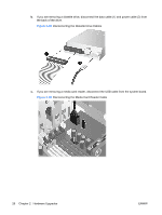
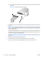
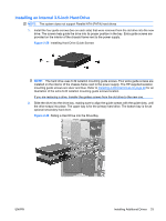
Installing an External 5.25-inch or 3.5-inch Drive NOTE: The system does not support Parallel ATA (PATA) optical drives. 1. Install the four guide screws (two on each side) that were removed from the old drive into the new drive. The screws help guide the drive into its proper position in the bay. Extra guide screws are provided on the interior of the chassis frame next to the power supply. Figure 2-21 Installing Guide Screws (Optical Drive Shown) NOTE: Optical drives, diskette drives, and media card readers use M3 metric guide screws. Four extra metric guide screws are provided on the interior of the chassis frame next to the power supply. The HP-supplied metric screws are black. Refer to Installing Additional Drives on page 22 for an illustration of the extra M3 metric guide screws location. If you are replacing a drive, transfer the guides screws from the old drive to the new one. 2. If necessary, remove the appropriate drive bezel blank from the front bezel by pressing the two retaining tabs towards the outer left edge of the bezel (1) and pull the bezel blank inwards to remove it (2). Figure 2-22 Removing Bezel Blanks 28 Chapter 2 Hardware Upgrades ENWW
-
 1
1 -
2
-
3
-
4
-
5
-
6
-
7
-
8
-
9
-
10
-
11
-
12
-
13
-
14
-
15
-
16
-
17
-
18
-
19
-
20
-
21
-
22
-
23
-
24
-
25
-
26
-
27
-
28
-
 29
29 -
 30
30 -
 31
31 -
 32
32 -
 33
33 -
 34
34 -
 35
35 -
 36
36 -
 37
37 -
 38
38 -
 39
39 -
40
-
41
-
42
-
43
-
44
-
45
-
46
-
47
-
48
-
49
-
50
-
51
-
52
-
53
-
54
-
55
-
56
-
57
-
58
 |
 |