HP ENVY 13-y000 Maintenance and Service Guide - Page 43
Remove the four Phillips PM2.5×4.1 broad head screws, from the retention clip that secures it.
 |
View all HP ENVY 13-y000 manuals
Add to My Manuals
Save this manual to your list of manuals |
Page 43 highlights
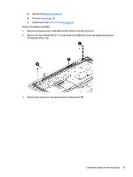
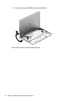
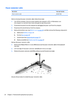
a. Battery (see Battery on page 22) b. Fan (see Fan on page 30) c. System board (see System board on page 31) Remove the display assembly: 1. Release the display panel cable (1) from the retention clip that secures it. 2. Remove the four Phillips PM2.5×4.1 broad head screws (2) that secure the display assembly to the keyboard/top cover. 3. Position the computer in the entertainment configuration (1). Component replacement procedures 35
-
 1
1 -
2
-
3
-
4
-
5
-
6
-
7
-
8
-
9
-
10
-
11
-
12
-
13
-
14
-
15
-
16
-
17
-
18
-
19
-
20
-
21
-
22
-
23
-
24
-
25
-
26
-
27
-
28
-
29
-
30
-
31
-
32
-
33
-
34
-
35
-
36
-
37
-
 38
38 -
 39
39 -
 40
40 -
 41
41 -
 42
42 -
 43
43 -
 44
44 -
 45
45 -
 46
46 -
 47
47 -
 48
48 -
49
-
50
-
51
-
52
-
53
-
54
-
55
-
56
-
57
-
58
-
59
-
60
-
61
-
62
-
63
-
64
 |
 |

a.
Battery (see
Battery
on page
22
)
b.
Fan (see
Fan
on page
30
)
c.
System board (see
System board
on page
31
)
Remove the display assembly:
1.
Release the display panel cable
(1)
from the retention clip that secures it.
2.
Remove the four Phillips PM2.5×4.1 broad head screws
(2)
that secure the display assembly to
the keyboard/top cover.
3.
Position the computer in the entertainment
configuration
(1)
.
Component replacement procedures
35