HP ENVY 13-y000 Maintenance and Service Guide - Page 46
Power connector cable, Remove the power connector cable
 |
View all HP ENVY 13-y000 manuals
Add to My Manuals
Save this manual to your list of manuals |
Page 46 highlights
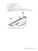
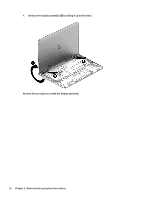
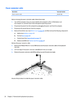
Power connector cable Description Power connector cable Spare part number 800229-002 Before removing the power connector cable, follow these steps: 1. Turn off the computer. If you are unsure whether the computer is off or in Hibernation, turn the computer on, and then shut it down through the operating system. 2. Disconnect the power from the computer by unplugging the power cord from the computer. 3. Disconnect all external devices from the computer. 4. Remove the bottom cover (see Bottom cover on page 20), and then remove the following components: a. Battery (see Battery on page 22) b. Fan (see Fan on page 30) c. System board (see System board on page 31) d. Display assembly (see Display assembly on page 34) Remove the power connector cable: 1. Remove the Phillips PM2.0×4.1 screw (1) that secures the power connector cable to the keyboard/ top cover. 2. Lift front edge of the power connector cable (2) until it rests at an angle. 3. Remove the power connector cable (3) by sliding it up and forward at an angle. Reverse this procedure to install the power connector cable. 38 Chapter 5 Removal and replacement procedures
-
 1
1 -
2
-
3
-
4
-
5
-
6
-
7
-
8
-
9
-
10
-
11
-
12
-
13
-
14
-
15
-
16
-
17
-
18
-
19
-
20
-
21
-
22
-
23
-
24
-
25
-
26
-
27
-
28
-
29
-
30
-
31
-
32
-
33
-
34
-
35
-
36
-
37
-
38
-
39
-
40
-
 41
41 -
 42
42 -
 43
43 -
 44
44 -
 45
45 -
 46
46 -
 47
47 -
 48
48 -
 49
49 -
 50
50 -
 51
51 -
52
-
53
-
54
-
55
-
56
-
57
-
58
-
59
-
60
-
61
-
62
-
63
-
64
 |
 |
