HP ENVY 15-q300 ENVY Notebook Maintenance and Service Guide - Page 47
Flex the inside edges of the top edge, secure the display bezel to the display assembly.
 |
View all HP ENVY 15-q300 manuals
Add to My Manuals
Save this manual to your list of manuals |
Page 47 highlights
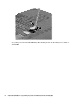
9. Remove the display assembly (2) from the computer. NOTE: Steps 10 through 16 apply only to computer models equipped with an Intel processor. 10. If it is necessary to replace the display bezel or any of the display assembly subcomponents: a. Remove the two screw covers (1) and the four Phillips PM2.5×3.2 broad head screws (2) that secure the display bezel to the display assembly. The screw covers are available in the Rubber Kit, spare part number 720559-001. b. Flex the inside edges of the top edge (1), the left and right sides (2), and the bottom edge (3) of the display bezel until the bezel disengages from the display enclosure. Component replacement procedures 39
-
 1
1 -
2
-
3
-
4
-
5
-
6
-
7
-
8
-
9
-
10
-
11
-
12
-
13
-
14
-
15
-
16
-
17
-
18
-
19
-
20
-
21
-
22
-
23
-
24
-
25
-
26
-
27
-
28
-
29
-
30
-
31
-
32
-
33
-
34
-
35
-
36
-
37
-
38
-
39
-
40
-
41
-
 42
42 -
 43
43 -
 44
44 -
 45
45 -
 46
46 -
 47
47 -
 48
48 -
 49
49 -
 50
50 -
 51
51 -
 52
52 -
53
-
54
-
55
-
56
-
57
-
58
-
59
-
60
-
61
-
62
-
63
-
64
-
65
-
66
-
67
-
68
-
69
-
70
-
71
-
72
-
73
-
74
-
75
-
76
-
77
-
78
-
79
-
80
-
81
-
82
-
83
-
84
-
85
-
86
-
87
-
88
-
89
-
90
-
91
-
92
-
93
-
94
-
95
-
96
 |
 |

9.
Remove the display assembly
(2)
from the computer.
NOTE:
Steps 10 through 16 apply only to computer models equipped with an Intel processor.
10.
If it is necessary to replace the display bezel or any of the display assembly subcomponents:
a.
Remove the two screw covers
(1)
and the four Phillips PM2.5×3.2 broad head screws
(2)
that
secure the display bezel to the display assembly.
The screw covers are available in the Rubber Kit, spare part number 720559-001.
b.
Flex the inside edges of the top edge
(1)
, the left and right sides
(2)
, and the bottom edge
(3)
of
the display bezel until the bezel disengages from the display enclosure.
Component replacement procedures
39