HP ENVY TouchSmart 15-j078ca HP ENVY 15 Notebook PC and HP ENVY TouchSmart 15 - Page 80
Heat sink, Steps 2 and 3 apply to computer models equipped with an AMD processor and
 |
View all HP ENVY TouchSmart 15-j078ca manuals
Add to My Manuals
Save this manual to your list of manuals |
Page 80 highlights
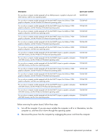
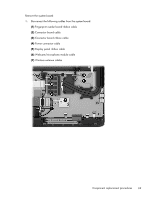
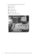
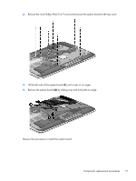
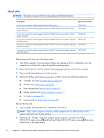
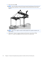
Heat sink NOTE: The heat sink spare part kit includes replacement thermal material. Description Spare part number For use only on computer models equipped with an AMD processor 720576-001 For use only on computer models equipped with the Intel HM87 chipset and a GeForce 750M graphics subsystem 720542-001 For use only on computer models equipped with the Intel HM87 chipset and a GeForce 740M graphics subsystem 722389-001 For use only on computer models equipped with the Intel HM87 chipset and a graphics subsystem 720541-001 with UMA memory For use only on computer models equipped with the Intel HM77 chipset and a graphics subsystem 720540-001 with discrete memory For use only on computer models equipped with the Intel HM77 chipset and a graphics subsystem 720539-001 with UMA memory Before removing the heat sink, follow these steps: 1. Turn off the computer. If you are unsure whether the computer is off or in Hibernation, turn the computer on, and then shut it down through the operating system. 2. Disconnect the power from the computer by unplugging the power cord from the computer. 3. Disconnect all external devices from the computer. 4. Remove the battery (see Battery on page 43), and then remove the following components: a. Solid-state drive (see Solid-state drive on page 44) b. Hard drive (see Hard drive on page 47) c. Base enclosure (see Base enclosure on page 55) d. Display assembly (see Display assembly on page 57) e. Fan (see Fan on page 65) f. System board (see System board on page 66) Remove the heat sink: 1. Turn the system board upside down, with the front toward you. NOTE: Steps 2 and 3 apply to computer models equipped with an AMD processor and a graphics subsystem with discrete memory. 2. Following the 1 through 7 sequence stamped into the heat sink, loosen the four Phillips PM2.0×11.0 captive screws (2) and the three Phillips PM2.0×7.5 captive screws (3) that secure the heat sink to the system board. 72 Chapter 6 Removal and replacement procedures for Authorized Service Provider parts
-
 1
1 -
2
-
3
-
4
-
5
-
6
-
7
-
8
-
9
-
10
-
11
-
12
-
13
-
14
-
15
-
16
-
17
-
18
-
19
-
20
-
21
-
22
-
23
-
24
-
25
-
26
-
27
-
28
-
29
-
30
-
31
-
32
-
33
-
34
-
35
-
36
-
37
-
38
-
39
-
40
-
41
-
42
-
43
-
44
-
45
-
46
-
47
-
48
-
49
-
50
-
51
-
52
-
53
-
54
-
55
-
56
-
57
-
58
-
59
-
60
-
61
-
62
-
63
-
64
-
65
-
66
-
67
-
68
-
69
-
70
-
71
-
72
-
73
-
74
-
 75
75 -
 76
76 -
 77
77 -
 78
78 -
 79
79 -
 80
80 -
 81
81 -
 82
82 -
 83
83 -
 84
84 -
 85
85 -
86
-
87
-
88
-
89
-
90
-
91
-
92
-
93
-
94
-
95
-
96
-
97
-
98
-
99
-
100
-
101
-
102
-
103
-
104
-
105
-
106
-
107
-
108
-
109
-
110
-
111
-
112
-
113
-
114
-
115
-
116
-
117
-
118
-
119
-
120
-
121
-
122
-
123
-
124
-
125
-
126
 |
 |