HP ENVY TouchSmart 15-j078ca HP ENVY 15 Notebook PC and HP ENVY TouchSmart 15 - Page 88
Connector board, from the system board.
 |
View all HP ENVY TouchSmart 15-j078ca manuals
Add to My Manuals
Save this manual to your list of manuals |
Page 88 highlights
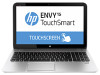
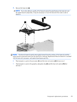
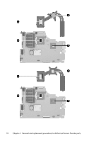
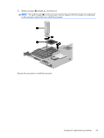
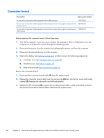
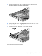
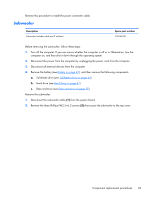
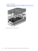
Connector board Description Spare part number For use only on computer models equipped with an AMD processor 720579-001 For use only on computer models equipped with an Intel processor and a graphics subsystem with 723372-001 discrete memory For use only on computer models equipped with an Intel processor and a graphics subsystem with 720554-001 UMA memory Before removing the connector board, follow these steps: 1. Turn off the computer. If you are unsure whether the computer is off or in Hibernation, turn the computer on, and then shut it down through the operating system. 2. Disconnect the power from the computer by unplugging the power cord from the computer. 3. Disconnect all external devices from the computer. 4. Remove the battery (see Battery on page 43), and then remove the following components: a. Solid-state drive (see Solid-state drive on page 44) b. Hard drive (see Hard drive on page 47) c. Base enclosure (see Base enclosure on page 55) Remove the connector board: 1. Disconnect the connector board cable (1) from the system board. 2. Release the connector board cable from the routing clips (2) built into the top cover and routing channel (3) between the subwoofer and left front speaker. 3. Release the ZIF connector (4) to which the connector board ribbon cable is attached, and then disconnect the connector board ribbon cable from the system board. 80 Chapter 6 Removal and replacement procedures for Authorized Service Provider parts
-
 1
1 -
2
-
3
-
4
-
5
-
6
-
7
-
8
-
9
-
10
-
11
-
12
-
13
-
14
-
15
-
16
-
17
-
18
-
19
-
20
-
21
-
22
-
23
-
24
-
25
-
26
-
27
-
28
-
29
-
30
-
31
-
32
-
33
-
34
-
35
-
36
-
37
-
38
-
39
-
40
-
41
-
42
-
43
-
44
-
45
-
46
-
47
-
48
-
49
-
50
-
51
-
52
-
53
-
54
-
55
-
56
-
57
-
58
-
59
-
60
-
61
-
62
-
63
-
64
-
65
-
66
-
67
-
68
-
69
-
70
-
71
-
72
-
73
-
74
-
75
-
76
-
77
-
78
-
79
-
80
-
81
-
82
-
 83
83 -
 84
84 -
 85
85 -
 86
86 -
 87
87 -
 88
88 -
 89
89 -
 90
90 -
 91
91 -
 92
92 -
 93
93 -
94
-
95
-
96
-
97
-
98
-
99
-
100
-
101
-
102
-
103
-
104
-
105
-
106
-
107
-
108
-
109
-
110
-
111
-
112
-
113
-
114
-
115
-
116
-
117
-
118
-
119
-
120
-
121
-
122
-
123
-
124
-
125
-
126
 |
 |