HP ENVY dv7-7227cl HP ENVY dv7 Notebook PC Maintenance and Service Guide IMPOR - Page 95
until you hear a click., Lift the processor
 |
View all HP ENVY dv7-7227cl manuals
Add to My Manuals
Save this manual to your list of manuals |
Page 95 highlights
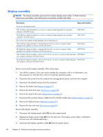
c. Keyboard (see Keyboard on page 59) d. Top cover (see Top cover on page 63) e. System board (see System board on page 77) f. Fan/heat sink assembly (see Fan/heat sink assembly on page 81) Remove the processor: 1. Turn the system board upside down, with the front toward you. 2. Use a flat-bladed screw driver (1) to turn the processor locking screw one-half turn counterclockwise (2), until you hear a click. 3. Lift the processor (3) straight up, and remove it. NOTE: The gold triangle (4) on the processor must be aligned with the triangle icon embossed on the processor socket when you install the processor. Reverse this procedure to install the processor. Component replacement procedures 87
-
 1
1 -
2
-
3
-
4
-
5
-
6
-
7
-
8
-
9
-
10
-
11
-
12
-
13
-
14
-
15
-
16
-
17
-
18
-
19
-
20
-
21
-
22
-
23
-
24
-
25
-
26
-
27
-
28
-
29
-
30
-
31
-
32
-
33
-
34
-
35
-
36
-
37
-
38
-
39
-
40
-
41
-
42
-
43
-
44
-
45
-
46
-
47
-
48
-
49
-
50
-
51
-
52
-
53
-
54
-
55
-
56
-
57
-
58
-
59
-
60
-
61
-
62
-
63
-
64
-
65
-
66
-
67
-
68
-
69
-
70
-
71
-
72
-
73
-
74
-
75
-
76
-
77
-
78
-
79
-
80
-
81
-
82
-
83
-
84
-
85
-
86
-
87
-
88
-
89
-
 90
90 -
 91
91 -
 92
92 -
 93
93 -
 94
94 -
 95
95 -
 96
96 -
 97
97 -
 98
98 -
 99
99 -
 100
100 -
101
-
102
-
103
-
104
-
105
-
106
-
107
-
108
-
109
-
110
-
111
-
112
-
113
-
114
-
115
-
116
-
117
-
118
-
119
-
120
-
121
-
122
-
123
-
124
-
125
-
126
-
127
-
128
-
129
 |
 |

c.
Keyboard (see
Keyboard
on page
59
)
d.
Top cover (see
Top cover
on page
63
)
e.
System board (see
System board
on page
77
)
f.
Fan/heat sink assembly (see
Fan/heat sink assembly
on page
81
)
Remove the processor:
1.
Turn the system board upside down, with the front toward you.
2.
Use a flat-bladed screw driver
(1)
to turn the processor locking screw one-half turn
counterclockwise
(2)
, until you hear a click.
3.
Lift the processor
(3)
straight up, and remove it.
NOTE:
The gold triangle
(4)
on the processor must be aligned with the triangle icon embossed
on the processor socket when you install the processor.
Reverse this procedure to install the processor.
Component replacement procedures
87