HP ENVY m4-1100 HP ENVY m4 Notebook PC Maintenance and Service Guide - Page 47
by pulling the module away from the slot at an angle., Remove the WLAN module
 |
View all HP ENVY m4-1100 manuals
Add to My Manuals
Save this manual to your list of manuals |
Page 47 highlights
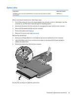
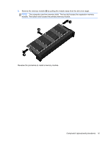
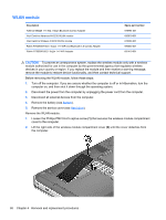
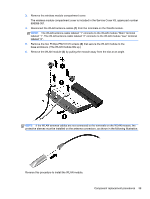
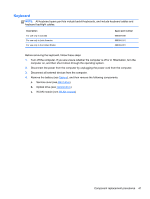
3. Remove the wireless module compartment cover. The wireless module compartment cover is included in the Service Cover Kit, spare part number 698086-001. 4. Disconnect the WLAN antenna cables (1) from the terminals on the WLAN module. NOTE: The WLAN antenna cable labeled "1" connects to the WLAN module "Main" terminal labeled "1". The WLAN antenna cable labeled "2" connects to the WLAN module "Aux" terminal labeled "2". 5. Remove the two Phillips PM2.0×3.5 screws (2) that secure the WLAN module to the base enclosure. (The WLAN module tilts up.) 6. Remove the WLAN module (3) by pulling the module away from the slot at an angle. NOTE: If the WLAN antenna cables are not connected to the terminals on the WLAN module, the protective sleeves must be installed on the antenna connectors, as shown in the following illustration. Reverse this procedure to install the WLAN module. Component replacement procedures 39
-
 1
1 -
2
-
3
-
4
-
5
-
6
-
7
-
8
-
9
-
10
-
11
-
12
-
13
-
14
-
15
-
16
-
17
-
18
-
19
-
20
-
21
-
22
-
23
-
24
-
25
-
26
-
27
-
28
-
29
-
30
-
31
-
32
-
33
-
34
-
35
-
36
-
37
-
38
-
39
-
40
-
41
-
 42
42 -
 43
43 -
 44
44 -
 45
45 -
 46
46 -
 47
47 -
 48
48 -
 49
49 -
 50
50 -
 51
51 -
 52
52 -
53
-
54
-
55
-
56
-
57
-
58
-
59
-
60
-
61
-
62
-
63
-
64
-
65
-
66
-
67
-
68
-
69
-
70
-
71
-
72
-
73
-
74
-
75
-
76
-
77
-
78
-
79
-
80
-
81
-
82
-
83
-
84
-
85
-
86
-
87
-
88
-
89
-
90
-
91
-
92
-
93
-
94
-
95
-
96
-
97
-
98
 |
 |
