HP ENVY m6-1205dx HP ENVY m6 Notebook PC Maintenance and Service Guide - Page 84
Disconnect the power connector cable, Close the computer.
 |
View all HP ENVY m6-1205dx manuals
Add to My Manuals
Save this manual to your list of manuals |
Page 84 highlights
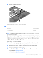
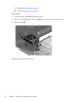
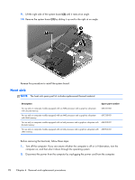
NOTE: When replacing the system board, be sure that the following components are removed from the defective system board and installed on the replacement system board: ● Memory module (see Memory module on page 55) ● Heat sink (see Heat sink on page 78) ● Processor (see Processor on page 81) Remove the system board: 1. Close the computer. 2. Turn the computer upside down, with the front toward you. 3. Disconnect the power connector cable (1) and the RTC battery (2) cable from the system board. 76 Chapter 4 Removal and replacement procedures
-
 1
1 -
2
-
3
-
4
-
5
-
6
-
7
-
8
-
9
-
10
-
11
-
12
-
13
-
14
-
15
-
16
-
17
-
18
-
19
-
20
-
21
-
22
-
23
-
24
-
25
-
26
-
27
-
28
-
29
-
30
-
31
-
32
-
33
-
34
-
35
-
36
-
37
-
38
-
39
-
40
-
41
-
42
-
43
-
44
-
45
-
46
-
47
-
48
-
49
-
50
-
51
-
52
-
53
-
54
-
55
-
56
-
57
-
58
-
59
-
60
-
61
-
62
-
63
-
64
-
65
-
66
-
67
-
68
-
69
-
70
-
71
-
72
-
73
-
74
-
75
-
76
-
77
-
78
-
 79
79 -
 80
80 -
 81
81 -
 82
82 -
 83
83 -
 84
84 -
 85
85 -
 86
86 -
 87
87 -
 88
88 -
 89
89 -
90
-
91
-
92
-
93
-
94
-
95
-
96
-
97
-
98
-
99
-
100
-
101
-
102
-
103
-
104
-
105
-
106
-
107
-
108
-
109
-
110
-
111
-
112
-
113
-
114
-
115
-
116
-
117
-
118
-
119
-
120
-
121
-
122
-
123
-
124
-
125
 |
 |
NOTE:
When replacing the system board, be sure that the following components are removed from
the defective system board and installed on the replacement system board:
●
Memory module (see
Memory module
on page
55
)
●
Heat sink (see
Heat sink
on page
78
)
●
Processor (see
Processor
on page
81
)
Remove the system board:
1.
Close the computer.
2.
Turn the computer upside down, with the front toward you.
3.
Disconnect the power connector cable
(1)
and the RTC battery
(2)
cable from the system board.
76
Chapter 4
Removal and replacement procedures