HP Engage Flex Pro G2 Maintenance and Service Guide - Page 57
Processor, to its fully open position.
 |
View all HP Engage Flex Pro G2 manuals
Add to My Manuals
Save this manual to your list of manuals |
Page 57 highlights
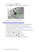
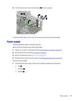
3. Thoroughly clean and replace the thermal grease from the surfaces on the system board and heat sink each time the heat sink is removed. Be sure that thermal grease is installed on the heat sink as shown in the following illustration. To install the heat sink, reverse the removal procedures. Processor To remove the processor, use these procedures. Before removing the processor, follow these steps: 1. Prepare the computer for disassembly (see Preparation for disassembly on page 20). 2. Remove the access panel (see Access panel on page 21). 3. Remove the fan duct (see Fan duct on page 47). 4. Remove the heat sink (see Heat sink on page 49). Remove the processor: 1. Pull the locking lever (1) away from the processor, and then rotate the lever to its full open position. 2. Raise and rotate the microprocessor retainer (2) to its fully open position. 3. Carefully lift the processor (3) from the socket. IMPORTANT: Do not handle the pins in the processor socket. These pins are fragile, and handling them could cause irreparable damage. If pins are damaged, you might have to replace the system board. 50 Chapter 4 Removal and replacement procedures
-
 1
1 -
2
-
3
-
4
-
5
-
6
-
7
-
8
-
9
-
10
-
11
-
12
-
13
-
14
-
15
-
16
-
17
-
18
-
19
-
20
-
21
-
22
-
23
-
24
-
25
-
26
-
27
-
28
-
29
-
30
-
31
-
32
-
33
-
34
-
35
-
36
-
37
-
38
-
39
-
40
-
41
-
42
-
43
-
44
-
45
-
46
-
47
-
48
-
49
-
50
-
51
-
 52
52 -
 53
53 -
 54
54 -
 55
55 -
 56
56 -
 57
57 -
 58
58 -
 59
59 -
 60
60 -
 61
61 -
 62
62 -
63
-
64
-
65
-
66
-
67
-
68
-
69
-
70
-
71
-
72
-
73
-
74
-
75
-
76
-
77
-
78
-
79
-
80
-
81
-
82
-
83
-
84
-
85
-
86
-
87
-
88
-
89
-
90
-
91
-
92
-
93
-
94
-
95
-
96
-
97
-
98
-
99
-
100
-
101
-
102
-
103
-
104
-
105
-
106
-
107
-
108
-
109
-
110
-
111
-
112
-
113
-
114
-
115
-
116
-
117
 |
 |
