HP Engage Flex Pro G2 Maintenance and Service Guide - Page 62
Power supply
 |
View all HP Engage Flex Pro G2 manuals
Add to My Manuals
Save this manual to your list of manuals |
Page 62 highlights
5. Remove the connector assembly and cables (5) from the computer. To install the WLAN antennas and external connectors, reverse the removal procedure. Power supply To remove the power supply, use these procedures. Before removing the power supply, follow these steps: 1. Prepare the computer for disassembly (see Preparation for disassembly on page 20). 2. Remove the access panel (see Access panel on page 21). 3. Remove the optical drive (see Optical drive on page 23). 4. Rotate the drive cage to the upright position (see Rotating the drive cage on page 26). Remove the power supply: 1. Disconnect the power supply cables from the following system board connectors: ● PWR (1) ● PWRCMD (2) ● PWRCPU (3) Power supply 55
-
 1
1 -
2
-
3
-
4
-
5
-
6
-
7
-
8
-
9
-
10
-
11
-
12
-
13
-
14
-
15
-
16
-
17
-
18
-
19
-
20
-
21
-
22
-
23
-
24
-
25
-
26
-
27
-
28
-
29
-
30
-
31
-
32
-
33
-
34
-
35
-
36
-
37
-
38
-
39
-
40
-
41
-
42
-
43
-
44
-
45
-
46
-
47
-
48
-
49
-
50
-
51
-
52
-
53
-
54
-
55
-
56
-
 57
57 -
 58
58 -
 59
59 -
 60
60 -
 61
61 -
 62
62 -
 63
63 -
 64
64 -
 65
65 -
 66
66 -
 67
67 -
68
-
69
-
70
-
71
-
72
-
73
-
74
-
75
-
76
-
77
-
78
-
79
-
80
-
81
-
82
-
83
-
84
-
85
-
86
-
87
-
88
-
89
-
90
-
91
-
92
-
93
-
94
-
95
-
96
-
97
-
98
-
99
-
100
-
101
-
102
-
103
-
104
-
105
-
106
-
107
-
108
-
109
-
110
-
111
-
112
-
113
-
114
-
115
-
116
-
117
 |
 |

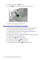
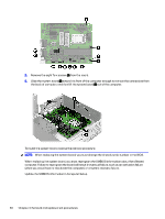
5.
Remove the connector assembly and cables
(5)
from the computer.
To install the WLAN antennas and external connectors, reverse the removal procedure.
Power supply
To remove the power supply, use these procedures.
Before removing the power supply, follow these steps:
1.
Prepare the computer for disassembly (see
Preparation for disassembly
on page
20
).
2.
Remove the access panel (see
Access panel
on page
21
).
3.
Remove the optical drive (see
Optical drive
on page
23
).
4.
Rotate the drive cage to the upright position (see
Rotating the drive cage
on page
26
).
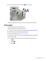
Remove the power supply:
1.
Disconnect the power supply cables from the following system board connectors:
●
PWR
(1)
●
PWRCMD
(2)
●
PWRCPU
(3)
Power supply
55