HP Evo n1000v Compaq Notebook Series, Evo N1000 and Presario 1500 Maintenance - Page 108
Removing a Mini PCI Communications Board
 |
View all HP Evo n1000v manuals
Add to My Manuals
Save this manual to your list of manuals |
Page 108 highlights
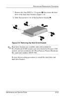
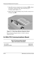
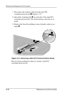
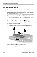
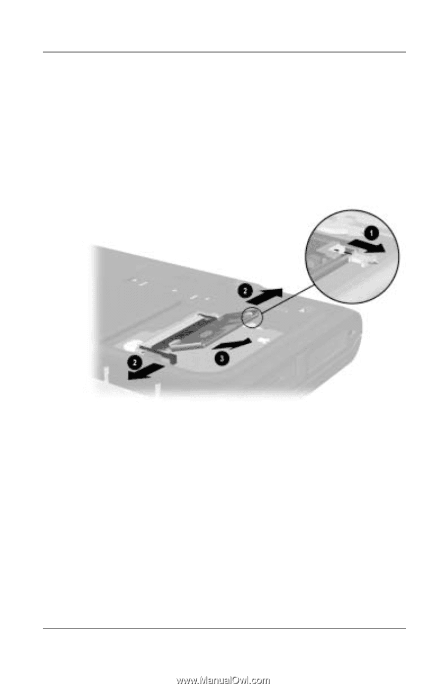
Removal and Replacement Procedures 7. Disconnect the modem cable from the mini PCI communications board 1 (Figure 5-13). 8. Spread the retaining tabs 2 on each side of the mini PCI communications board. The board releases and rests at an angle. 9. Remove the board by pulling it away from the socket at an angle 3. Figure 5-13. Removing a Mini PCI Communications Board Reverse the preceding procedures to install a mini PCI communications board. 5-16 Maintenance and Service Guide
-
 1
1 -
2
-
3
-
4
-
5
-
6
-
7
-
8
-
9
-
10
-
11
-
12
-
13
-
14
-
15
-
16
-
17
-
18
-
19
-
20
-
21
-
22
-
23
-
24
-
25
-
26
-
27
-
28
-
29
-
30
-
31
-
32
-
33
-
34
-
35
-
36
-
37
-
38
-
39
-
40
-
41
-
42
-
43
-
44
-
45
-
46
-
47
-
48
-
49
-
50
-
51
-
52
-
53
-
54
-
55
-
56
-
57
-
58
-
59
-
60
-
61
-
62
-
63
-
64
-
65
-
66
-
67
-
68
-
69
-
70
-
71
-
72
-
73
-
74
-
75
-
76
-
77
-
78
-
79
-
80
-
81
-
82
-
83
-
84
-
85
-
86
-
87
-
88
-
89
-
90
-
91
-
92
-
93
-
94
-
95
-
96
-
97
-
98
-
99
-
100
-
101
-
102
-
 103
103 -
 104
104 -
 105
105 -
 106
106 -
 107
107 -
 108
108 -
 109
109 -
 110
110 -
 111
111 -
 112
112 -
 113
113 -
114
-
115
-
116
-
117
-
118
-
119
-
120
-
121
-
122
-
123
-
124
-
125
-
126
-
127
-
128
-
129
-
130
-
131
-
132
-
133
-
134
-
135
-
136
-
137
-
138
-
139
-
140
-
141
-
142
-
143
-
144
-
145
-
146
-
147
-
148
-
149
-
150
-
151
-
152
-
153
-
154
-
155
-
156
-
157
-
158
-
159
-
160
-
161
-
162
-
163
-
164
-
165
-
166
-
167
-
168
-
169
-
170
-
171
-
172
-
173
-
174
-
175
-
176
-
177
-
178
-
179
-
180
-
181
-
182
-
183
-
184
-
185
-
186
-
187
-
188
-
189
-
190
-
191
-
192
-
193
-
194
-
195
-
196
-
197
-
198
-
199
-
200
-
201
-
202
-
203
-
204
 |
 |
5–16
Maintenance and Service Guide
Removal and Replacement Procedures
7. Disconnect the modem cable from the mini PCI
communications board
1
(Figure 5-13).
8. Spread the retaining tabs
2
on each side of the mini PCI
communications board. The board releases and rests at an
angle.
9. Remove the board by pulling it away from the socket at an
angle
3
.
Figure 5-13. Removing a Mini PCI Communications Board
Reverse the preceding procedures to install a mini PCI
communications board.