HP Evo n1000v Compaq Notebook Series, Evo N1000 and Presario 1500 Maintenance - Page 123
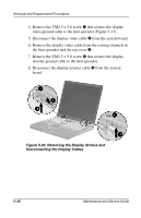
Removing the Display, Remove the four TM2.5 × 9.0 screws, that secure
 |
View all HP Evo n1000v manuals
Add to My Manuals
Save this manual to your list of manuals |
Page 123 highlights
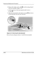
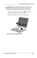
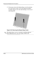
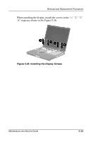
Removal and Replacement Procedures Ä CAUTION: Make sure the display is supported when removing the following screws. The display is secured to the computer only by these screws and will fall if not supported during screw removal. 9. Remove the four TM2.5 × 9.0 screws 1 that secure the display to the base enclosure (Figure 5-24). 10. Remove the display from the base enclosure 2. Figure 5-24. Removing the Display Maintenance and Service Guide 5-31
-
 1
1 -
2
-
3
-
4
-
5
-
6
-
7
-
8
-
9
-
10
-
11
-
12
-
13
-
14
-
15
-
16
-
17
-
18
-
19
-
20
-
21
-
22
-
23
-
24
-
25
-
26
-
27
-
28
-
29
-
30
-
31
-
32
-
33
-
34
-
35
-
36
-
37
-
38
-
39
-
40
-
41
-
42
-
43
-
44
-
45
-
46
-
47
-
48
-
49
-
50
-
51
-
52
-
53
-
54
-
55
-
56
-
57
-
58
-
59
-
60
-
61
-
62
-
63
-
64
-
65
-
66
-
67
-
68
-
69
-
70
-
71
-
72
-
73
-
74
-
75
-
76
-
77
-
78
-
79
-
80
-
81
-
82
-
83
-
84
-
85
-
86
-
87
-
88
-
89
-
90
-
91
-
92
-
93
-
94
-
95
-
96
-
97
-
98
-
99
-
100
-
101
-
102
-
103
-
104
-
105
-
106
-
107
-
108
-
109
-
110
-
111
-
112
-
113
-
114
-
115
-
116
-
117
-
 118
118 -
 119
119 -
 120
120 -
 121
121 -
 122
122 -
 123
123 -
 124
124 -
 125
125 -
 126
126 -
 127
127 -
 128
128 -
129
-
130
-
131
-
132
-
133
-
134
-
135
-
136
-
137
-
138
-
139
-
140
-
141
-
142
-
143
-
144
-
145
-
146
-
147
-
148
-
149
-
150
-
151
-
152
-
153
-
154
-
155
-
156
-
157
-
158
-
159
-
160
-
161
-
162
-
163
-
164
-
165
-
166
-
167
-
168
-
169
-
170
-
171
-
172
-
173
-
174
-
175
-
176
-
177
-
178
-
179
-
180
-
181
-
182
-
183
-
184
-
185
-
186
-
187
-
188
-
189
-
190
-
191
-
192
-
193
-
194
-
195
-
196
-
197
-
198
-
199
-
200
-
201
-
202
-
203
-
204
 |
 |
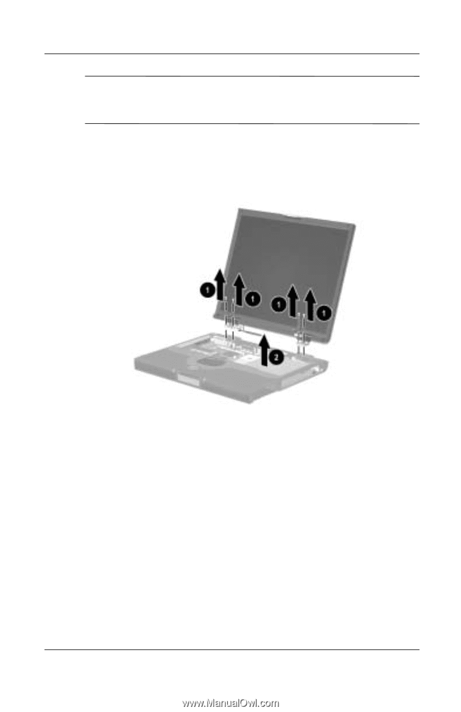
Removal and Replacement Procedures
Maintenance and Service Guide
5–31
Ä
CAUTION:
Make sure the display is supported when removing the
following screws. The display is secured to the computer only by
these screws and will fall if not supported during screw removal.
9. Remove the four TM2.5 × 9.0 screws
1
that secure the
display to the base enclosure (Figure 5-24).
10. Remove the display from the base enclosure
2
.
Figure 5-24. Removing the Display