HP Evo n1000v Compaq Notebook Series, Evo N1000 and Presario 1500 Maintenance - Page 202
PC Card slot, parts catalog
 |
View all HP Evo n1000v manuals
Add to My Manuals
Save this manual to your list of manuals |
Page 202 highlights
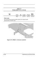
Index modem cable illustrated 3-18 removal 5-59 modem connector location 1-21 pin assignments A-2 monitor connector location 1-21 pin assignments A-5 mouse connector location 1-21 pin assignments A-3 N network connector location 1-21 pin assignment A-1 network, troubleshooting 2-30 nonfunctioning device, troubleshooting 2-18, 2-27 notebook specifications 6-1 num lock key 1-22 num lock light 1-24 numeric keypad 1-23 O operating system loading, troubleshooting 2-19 optical drive location 1-19 removal 5-7 spare part numbers 3-15, 3-21, 5-7 optical drive alignment rail illustrated 3-16 removal 5-56 P packing precautions 4-4 palm rest removal 5-34 spare part numbers 3-9, 5-34 parallel connector location 1-21 pin assignments A-4 parts catalog 3-1 password, clearing 1-16 PC Card eject button 1-21 PC Card slot 1-21 PC Card slot space saver 3-16 plastic parts 4-2 pointing device, troubleshooting 2-29 pointing stick board, removal 5-44 pointing stick board-to-TouchButton board cable illustrated 3-18 removal 5-43 port replicator, spare part numbers 3-22 power button 1-25 power cord, spare part numbers 3-22 power jack 1-20 power light 1-24 power management features 1-17 power, troubleshooting 2-12 power/Standby light 1-18, 1-25 Maintenance and Service Guide Index-5
-
 1
1 -
2
-
3
-
4
-
5
-
6
-
7
-
8
-
9
-
10
-
11
-
12
-
13
-
14
-
15
-
16
-
17
-
18
-
19
-
20
-
21
-
22
-
23
-
24
-
25
-
26
-
27
-
28
-
29
-
30
-
31
-
32
-
33
-
34
-
35
-
36
-
37
-
38
-
39
-
40
-
41
-
42
-
43
-
44
-
45
-
46
-
47
-
48
-
49
-
50
-
51
-
52
-
53
-
54
-
55
-
56
-
57
-
58
-
59
-
60
-
61
-
62
-
63
-
64
-
65
-
66
-
67
-
68
-
69
-
70
-
71
-
72
-
73
-
74
-
75
-
76
-
77
-
78
-
79
-
80
-
81
-
82
-
83
-
84
-
85
-
86
-
87
-
88
-
89
-
90
-
91
-
92
-
93
-
94
-
95
-
96
-
97
-
98
-
99
-
100
-
101
-
102
-
103
-
104
-
105
-
106
-
107
-
108
-
109
-
110
-
111
-
112
-
113
-
114
-
115
-
116
-
117
-
118
-
119
-
120
-
121
-
122
-
123
-
124
-
125
-
126
-
127
-
128
-
129
-
130
-
131
-
132
-
133
-
134
-
135
-
136
-
137
-
138
-
139
-
140
-
141
-
142
-
143
-
144
-
145
-
146
-
147
-
148
-
149
-
150
-
151
-
152
-
153
-
154
-
155
-
156
-
157
-
158
-
159
-
160
-
161
-
162
-
163
-
164
-
165
-
166
-
167
-
168
-
169
-
170
-
171
-
172
-
173
-
174
-
175
-
176
-
177
-
178
-
179
-
180
-
181
-
182
-
183
-
184
-
185
-
186
-
187
-
188
-
189
-
190
-
191
-
192
-
193
-
194
-
195
-
196
-
 197
197 -
 198
198 -
 199
199 -
 200
200 -
 201
201 -
 202
202 -
 203
203 -
 204
204
 |
 |