HP G72-257CL Compaq Presario CQ72 Notebook PC and HP G72 Notebook PC - Mainten - Page 47
Component replacement procedures, Service tag - driver
 |
View all HP G72-257CL manuals
Add to My Manuals
Save this manual to your list of manuals |
Page 47 highlights
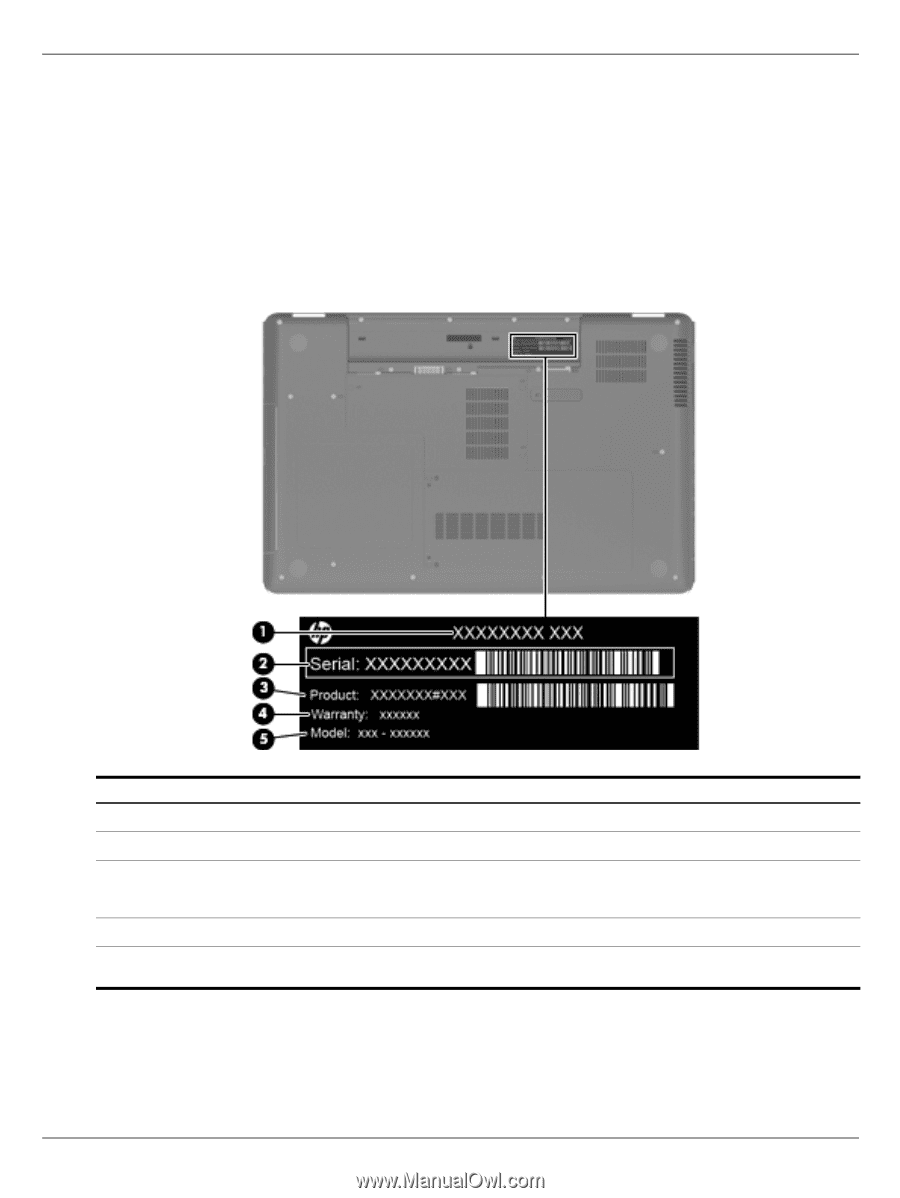
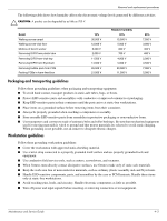
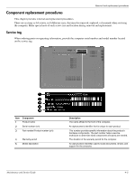
Removal and replacement procedures Component replacement procedures This chapter provides removal and replacement procedures. There are as many as 64 screws, in 8 different sizes, that must be removed, replaced, or loosened when servicing the computer. Make special note of each screw size and location during removal and replacement. Service tag When ordering parts or requesting information, provide the computer serial number and model number located on the service tag. Item Component 1 Product name 2 Serial number (s/n) 3 Part number/Product number (p/n) 4 Warranty period 5 Model description Description The name affixed to the front of the computer. An alphanumeric identifier that is unique to each product. This number provides specific information about the product's hardware components. The part number helps a service technician to determine what components and parts are needed. The duration of the warranty period for the computer. An alphanumeric identifier used to locate documents, drivers, and support for the computer. Maintenance and Service Guide 4-5
-
 1
1 -
2
-
3
-
4
-
5
-
6
-
7
-
8
-
9
-
10
-
11
-
12
-
13
-
14
-
15
-
16
-
17
-
18
-
19
-
20
-
21
-
22
-
23
-
24
-
25
-
26
-
27
-
28
-
29
-
30
-
31
-
32
-
33
-
34
-
35
-
36
-
37
-
38
-
39
-
40
-
41
-
 42
42 -
 43
43 -
 44
44 -
 45
45 -
 46
46 -
 47
47 -
 48
48 -
 49
49 -
 50
50 -
 51
51 -
 52
52 -
53
-
54
-
55
-
56
-
57
-
58
-
59
-
60
-
61
-
62
-
63
-
64
-
65
-
66
-
67
-
68
-
69
-
70
-
71
-
72
-
73
-
74
-
75
-
76
-
77
-
78
-
79
-
80
-
81
-
82
-
83
-
84
-
85
-
86
-
87
-
88
-
89
-
90
-
91
-
92
-
93
-
94
-
95
-
96
-
97
-
98
-
99
-
100
-
101
-
102
-
103
-
104
-
105
-
106
-
107
-
108
-
109
-
110
-
111
-
112
-
113
-
114
-
115
-
116
-
117
-
118
-
119
-
120
-
121
-
122
-
123
-
124
-
125
-
126
-
127
-
128
-
129
-
130
-
131
-
132
 |
 |