HP G72-257CL Compaq Presario CQ72 Notebook PC and HP G72 Notebook PC - Mainten - Page 99
Optical drive connector
 |
View all HP G72-257CL manuals
Add to My Manuals
Save this manual to your list of manuals |
Page 99 highlights
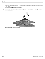
Optical drive connector Removal and replacement procedures Description Optical drive connector and cable (included in Cable Kit) Spare part number 600853-001 Before removing the optical drive connector: 1. Shut down the computer. If you are unsure whether the computer is off or in Hibernation, turn the computer on, and then shut it down through the operating system. 2. Disconnect all external devices connected to the computer. 3. Disconnect the power from the computer by first disconnecting the power cord from the AC outlet and then disconnecting the AC adapter from the computer. 4. Remove the battery (see "Battery" on page 4-7) 5. Remove the hard drive (see "Hard drive" on page 4-8). 6. Remove the memory module (see "Memory module" on page 4-11). 7. Remove the wireless module (see "Wireless module" on page 4-13). 8. Remove the optical drive (see "Optical drive" on page 4-16). 9. Remove the keyboard (see "Keyboard" on page 4-18). 10. Remove the top cover (see "Top cover" on page 4-23). 11. Remove the display assembly (see "Display assembly" on page 4-28). 12. Remove the sytem board (see "System board" on page 4-44). Maintenance and Service Guide 4-57
-
 1
1 -
2
-
3
-
4
-
5
-
6
-
7
-
8
-
9
-
10
-
11
-
12
-
13
-
14
-
15
-
16
-
17
-
18
-
19
-
20
-
21
-
22
-
23
-
24
-
25
-
26
-
27
-
28
-
29
-
30
-
31
-
32
-
33
-
34
-
35
-
36
-
37
-
38
-
39
-
40
-
41
-
42
-
43
-
44
-
45
-
46
-
47
-
48
-
49
-
50
-
51
-
52
-
53
-
54
-
55
-
56
-
57
-
58
-
59
-
60
-
61
-
62
-
63
-
64
-
65
-
66
-
67
-
68
-
69
-
70
-
71
-
72
-
73
-
74
-
75
-
76
-
77
-
78
-
79
-
80
-
81
-
82
-
83
-
84
-
85
-
86
-
87
-
88
-
89
-
90
-
91
-
92
-
93
-
 94
94 -
 95
95 -
 96
96 -
 97
97 -
 98
98 -
 99
99 -
 100
100 -
 101
101 -
 102
102 -
 103
103 -
 104
104 -
105
-
106
-
107
-
108
-
109
-
110
-
111
-
112
-
113
-
114
-
115
-
116
-
117
-
118
-
119
-
120
-
121
-
122
-
123
-
124
-
125
-
126
-
127
-
128
-
129
-
130
-
131
-
132
 |
 |
