HP Indigo W7250 Strain Gauge Second Transfer Measurement Service and Troublesh - Page 8
General Electronics - Signal flow diagram, Open loop second transfer pressure control
 |
View all HP Indigo W7250 manuals
Add to My Manuals
Save this manual to your list of manuals |
Page 8 highlights
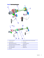
Figure 2-4 General Electronics - Signal flow diagram Open loop second transfer pressure control Two strain gages are connected to the front and the rear of the impression. The strain gages are wired into the IP and Feed drive (U15 & U17) analog input 7 and 3. Figure 2-5 Electrical Diagram - Rear Strain Gauge 6 Chapter 2 Introduction
-
 1
1 -
2
-
 3
3 -
 4
4 -
 5
5 -
 6
6 -
 7
7 -
 8
8 -
 9
9 -
 10
10 -
 11
11 -
 12
12 -
 13
13 -
14
-
15
 |
 |

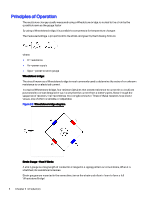
Figure 2-4
General Electronics — Signal flow diagram
Open loop second transfer pressure control
Two strain gages are connected to the front and the rear of the impression.
The strain gages are wired into the IP and Feed drive (U15 & U17) analog input 7 and 3.
Figure 2-5
Electrical Diagram — Rear Strain Gauge
6
Chapter 2
Introduction