HP Integrity rx5670 Hardware Installation Guide - HP Integrity rx5670 (A6837B/
HP Integrity rx5670 Manual
 |
View all HP Integrity rx5670 manuals
Add to My Manuals
Save this manual to your list of manuals |
HP Integrity rx5670 manual content summary:
- HP Integrity rx5670 | Hardware Installation Guide - HP Integrity rx5670 (A6837B/ - Page 1
hp Integrity rx5670 Hardware Installation Guide Product ID: A6837B/A6838B Manufacturing Part Number : A6837-96001 July 2003 USA © Copyright 2003 Hewlett-Packard Company. - HP Integrity rx5670 | Hardware Installation Guide - HP Integrity rx5670 (A6837B/ - Page 2
The HP Server Documentation CD-ROM has been provided with your server. It contains a complete documentation set for the server, including localized versions of key documents. Included on the CD-ROM are the Site Preparation and Operations and Maintenance guides, which contain in-depth troubleshooting - HP Integrity rx5670 | Hardware Installation Guide - HP Integrity rx5670 (A6837B/ - Page 3
Processor 37 Beep Codes 37 Common Installation Problems 38 The Server Does Not Power On-Power Supply Malfunction 38 The Server Does Not Power On-Power Supplies OK 38 The Server Powers On But Then Shuts Down with a Fault Light 38 hp Integrity rx5670 LED Indicators 39 Front Panel LEDs 39 - HP Integrity rx5670 | Hardware Installation Guide - HP Integrity rx5670 (A6837B/ - Page 4
Contents MP/SCSI Connections 60 LAN/SCSI Connections 60 Management Processor 60 Booting the Server 67 4 - HP Integrity rx5670 | Hardware Installation Guide - HP Integrity rx5670 (A6837B/ - Page 5
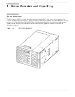
family architecture. The hp Integrity rx5670 accommodates up to 48 DIMMs and internal peripherals including disks and DVD ROM/Tape. Its high availability features include hot swap fans and power supplies, and hot plug internal disk drives. The supported operating systems include HP-UX, Windows, and - HP Integrity rx5670 | Hardware Installation Guide - HP Integrity rx5670 (A6837B/ - Page 6
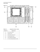
Overview and Unpacking Server Overview Figure 1-2 hp Integrity rx5670 (front view with bezel removed) A B F ever042 E Table 1-1 Important Items - Front Identifier Component A Front panel LEDs B Power switch C Removable media drive D Hot plug disk drives E Hot - HP Integrity rx5670 | Hardware Installation Guide - HP Integrity rx5670 (A6837B/ - Page 7
hp Integrity rx5670 (rear view) A B C D ever017 H Table 1-2 Important Items - Rear Identifier Component A NetRaid PCI card (optional, supported with Windows and Linux) B LAN/SCSI PCI card (required with all operating systems) C VGA/USB PCI card (required with Windows, optional for HP - HP Integrity rx5670 | Hardware Installation Guide - HP Integrity rx5670 (A6837B/ - Page 8
Server Overview and Unpacking Server Overview Figure 1-4 hp Integrity rx5670 Top Service Bay ever046 8 Chapter 1 - HP Integrity rx5670 | Hardware Installation Guide - HP Integrity rx5670 (A6837B/ - Page 9
Overview and Unpacking Server Overview hp Integrity rx5670 Top Service Bay Components B D C Table 1-3 ever038 Top Service Bay Components Identifier Component A Processor extender board B Memory extender board MX0 (required) C System baseboard D Memory extender board MX1 (optional - HP Integrity rx5670 | Hardware Installation Guide - HP Integrity rx5670 (A6837B/ - Page 10
Server Overview and Unpacking Server Overview Figure 1-6 hp Integrity rx5670 Side Service Bay A B 4x ever016 Table 1-4 Side Service Bay Components Identifier Component A Hot swap card cage fans B PCI backplane 10 Chapter 1 - HP Integrity rx5670 | Hardware Installation Guide - HP Integrity rx5670 (A6837B/ - Page 11
and return it to the shipping representative. NOTE The server may come already racked or ready for rack installation. Unpacking a Racked Server This section contains information pertaining to unpacking the hp Integrity rx5670 cabinet. WARNING Wear protective glasses while cutting the polystrap - HP Integrity rx5670 | Hardware Installation Guide - HP Integrity rx5670 (A6837B/ - Page 12
Overview and Unpacking Unpacking the Server 2. Lift the cardboard top cap from the shipping box. Figure 1-7 Removing the Polystraps and Cardboard fig013 3. Remove the corrugated wrap from the pallet. 4. Remove the - HP Integrity rx5670 | Hardware Installation Guide - HP Integrity rx5670 (A6837B/ - Page 13
from the pallet using a lifter, perform the following steps: WARNING Use caution when using a lifter. An hp Integrity rx5670 may weigh up to 175 pounds. Because of the weight of the server, it must be centered on the lifter forks before raising it off the pallet to avoid injury. Chapter 1 13 - HP Integrity rx5670 | Hardware Installation Guide - HP Integrity rx5670 (A6837B/ - Page 14
moving it over to the rack. Installing the Server into a Rack HP Rack Any hp Integrity rx5670 that is to be installed into a rack is shipped with equipment slides. With every set of slides comes an installation guide: hp Integrity rx5670 rack installation guide. Follow the steps in this installation - HP Integrity rx5670 | Hardware Installation Guide - HP Integrity rx5670 (A6837B/ - Page 15
the device can be safely installed into the server. Verify that the operating system supports installing disk drives while the operating system is running. If the operating system does not support this feature, shut down the operating system before attempting this procedure. Failure to observe - HP Integrity rx5670 | Hardware Installation Guide - HP Integrity rx5670 (A6837B/ - Page 16
view) ever011 Installing Hot Swap Power Supplies Power Supply Load Order There is no specific load order requirement for hot swap power supplies. However, the supported configuration of an hp Integrity rx5670 requires a minimum of two supplies be installed. A third, optional hot swap power supply - HP Integrity rx5670 | Hardware Installation Guide - HP Integrity rx5670 (A6837B/ - Page 17
power cord at the rear of the system if the system is powered down. Failure to observe this caution will result in damage to the server. Figure 2-2 Hot Swap Power Supply Installation ever041 Chapter 2 17 - HP Integrity rx5670 | Hardware Installation Guide - HP Integrity rx5670 (A6837B/ - Page 18
2-3 Power Cord Receptacles at Rear of Chassis ever017 1. Grasp the handle in one hand and support the hot swap power supply with the other. 2. Slide the hot swap power supply into the server. If the server is powered on, the hot swap power supply LED should illuminate immediately. 3. Tighten the - HP Integrity rx5670 | Hardware Installation Guide - HP Integrity rx5670 (A6837B/ - Page 19
Installing Additional Components Installing Power Supplies and Disk Drives Installing a Hot Plug Disk Drive To install a hot plug disk drive, perform the following steps: 1. Ensure that the hot plug disk drive latch is in the open/unlocked position. 2. Gently slide the hot plug disk drive into the - HP Integrity rx5670 | Hardware Installation Guide - HP Integrity rx5670 (A6837B/ - Page 20
Installing Additional Components Installing Power Supplies and Disk Drives NOTE Figure 2-4 When the disk drive is properly seated, the notch located at the top of the latch will lock onto the lip located at the top of the disk drive slot in the disk media housing. Disk Drive Installation ever004 - HP Integrity rx5670 | Hardware Installation Guide - HP Integrity rx5670 (A6837B/ - Page 21
to equipment. CAUTION Do not operate the server without the top cover in place. Operation of the server without the top cover in place will result in server failure. Operation of the server without the top cover in place will make the server susceptible to EMI problems. Observe all ESD safety - HP Integrity rx5670 | Hardware Installation Guide - HP Integrity rx5670 (A6837B/ - Page 22
Additional Components Installing Processors and Memory 2. Grasp the strap handle, raise the cover slightly, and pull the cover toward the front of the server to free the cover tabs from the slots in the rear of the chassis. Figure 2-5 Top Cover Removal Processor Extender Board Memory Extender - HP Integrity rx5670 | Hardware Installation Guide - HP Integrity rx5670 (A6837B/ - Page 23
Installing Processors and Memory Processor Installation Locations Processors are housed on the processor extender board located under the top cover in the top service bay. The processor extender board can hold one, two, three, or four processors. If fewer than four processors are installed to be - HP Integrity rx5670 | Hardware Installation Guide - HP Integrity rx5670 (A6837B/ - Page 24
Installing Additional Components Installing Processors and Memory 2. Pull up on the extraction levers to free the processor extender board from the socket located on the system baseboard. Figure 2-6 Processor Extender Board CPU0 CPU1 CPU2 CPU3 Extraction Lever Extraction Lever ever026 - HP Integrity rx5670 | Hardware Installation Guide - HP Integrity rx5670 (A6837B/ - Page 25
2) to align the CPU module with the extender board socket. 5. Carefully position the CPU module above the processor socket using the alignment guide pins (Figure 2-7, item 6) to align the processor connector with the extender board socket. 6. Using the alignment tabs on the processor socket, and - HP Integrity rx5670 | Hardware Installation Guide - HP Integrity rx5670 (A6837B/ - Page 26
Installing Additional Components Installing Processors and Memory NOTE When installing the processor retention cover, the screws should be tightened in sequence as shown in Figure 2-7. Each screw should be turned 2-3 times until all screws are bottomed out. Figure 2-7 Processor Installation 3 4 - HP Integrity rx5670 | Hardware Installation Guide - HP Integrity rx5670 (A6837B/ - Page 27
boards located in the top service bay. If only one memory server, or installing additional DIMMS, you can increase the amount of memory in your server. Several different DIMM sets are available. The DIMMs are listed in your hp Integrity rx5670 Operation and Maintenance Guide, and at http://www.hp - HP Integrity rx5670 | Hardware Installation Guide - HP Integrity rx5670 (A6837B/ - Page 28
Installing Additional Components Installing Processors and Memory Memory must be installed in groups of four identical DIMMs. For a minimally loaded system, DIMMs will be loaded in slots 0A, 0B, 0C, and 0D. This collection of slots is referred to as Rank 0. The next set of DIMMs loaded are installed - HP Integrity rx5670 | Hardware Installation Guide - HP Integrity rx5670 (A6837B/ - Page 29
3. Lift the memory extender board from the server chassis. Figure 2-9 Memory Extender Board Installing Additional Components Installing Processors and Memory Extraction Lever Extraction Lever DIMM Retainer Holding Screws ever035 Installing Memory To install - HP Integrity rx5670 | Hardware Installation Guide - HP Integrity rx5670 (A6837B/ - Page 30
the memory extender board extraction levers are positioned in the outward, unlocked position. 3. Align the memory extender board with the front and rear card guides. 4. Slide the memory extender board down until it begins to seat in the socket located on the system baseboard. 5. Push the extraction - HP Integrity rx5670 | Hardware Installation Guide - HP Integrity rx5670 (A6837B/ - Page 31
Installing Additional Components Installing Processors and Memory 2. Seat the top cover in the top of the service bay and tighten the captive T-15 screws that hold the top cover in place. Chapter 2 31 - HP Integrity rx5670 | Hardware Installation Guide - HP Integrity rx5670 (A6837B/ - Page 32
Installing PCI Cards This section provides information about installing PCI cards. PCI cards are located in the side service bay. WARNING Voltages are present at various locations within the server whenever an AC power source is connected. This voltage is present even when the main power switch is - HP Integrity rx5670 | Hardware Installation Guide - HP Integrity rx5670 (A6837B/ - Page 33
the PCI backplane. PCI slots 1 and 3 are dedicated for use by the servers core I/O cards. The core I/O functions are shared between two cards; an MP If the RAID card is not installed, slot 4 may be used for other supported PCI cards. PCI Card Performance Considerations Slot 2, which shares a 33 MHz - HP Integrity rx5670 | Hardware Installation Guide - HP Integrity rx5670 (A6837B/ - Page 34
a 500 MB/second peak data rate at 133 MHz. Installing a PCI Card The server may contain up to 12 PCI cards. PCI cards are located in the side service bay. WARNING Voltages are present at various locations within the server whenever an AC power source is connected. This voltage is present even when - HP Integrity rx5670 | Hardware Installation Guide - HP Integrity rx5670 (A6837B/ - Page 35
outside of the side fan housing. Orient the PCI card into its guide slot and push it into the server until the PCI card is seated in the PCI backplane card connector. Figure 2-12 Front PCI Card Guide Location PCI Card Guide frntpcigdeloc 3. Connect all external cables to the PCI card at the rear - HP Integrity rx5670 | Hardware Installation Guide - HP Integrity rx5670 (A6837B/ - Page 36
following steps: 1. Grasp the strap handle and insert the tabbed end of the side cover into the server chassis slots at the rear of the side service bay. 2. Push the side cover into the side service bay opening and fasten the captive T-15 screws that hold the side cover in place. 36 Chapter 2 - HP Integrity rx5670 | Hardware Installation Guide - HP Integrity rx5670 (A6837B/ - Page 37
information about troubleshooting can be found in the hp Integrity rx5670 Operation and Maintenance Guide. Error Messages Most server failures will not fix a problem, replacing the corresponding driver, receiver, or interconnecting cable will usually fix the problem.) Instructions for connecting a - HP Integrity rx5670 | Hardware Installation Guide - HP Integrity rx5670 (A6837B/ - Page 38
contains general procedures to help you locate installation problems. To troubleshoot an installation problem, perform the following checks in the order affect on the server. 4. Unplug the power cord, wait 20 seconds, plug the power cord in again, and restart the server. The Server Does Not Power On - HP Integrity rx5670 | Hardware Installation Guide - HP Integrity rx5670 (A6837B/ - Page 39
Troubleshooting hp Integrity rx5670 LED Indicators hp Integrity rx5670 LED Indicators The hp Integrity rx5670 includes LED indicators that show the health of the server. Front panel indicators show server status at a glance. LEDs within the server provide additional information. Front Panel LEDs - HP Integrity rx5670 | Hardware Installation Guide - HP Integrity rx5670 (A6837B/ - Page 40
Troubleshooting hp Integrity rx5670 LED Indicators The power LED should be lit while the server is operating. The remote LED will be on when remote access to the MP/SCSI card is enabled. Table 3-1 describes the power, run, attention, and fault LED - HP Integrity rx5670 | Hardware Installation Guide - HP Integrity rx5670 (A6837B/ - Page 41
Troubleshooting hp Integrity rx5670 LED Indicators Table 3-1 Power (Green) on on on on on on on up (non OS code). Non-critical operator intervention needed. Check console logs. Fault condition, can't boot. Other non-critical operator intervention needed. Check console logs. Unexpected reboot - HP Integrity rx5670 | Hardware Installation Guide - HP Integrity rx5670 (A6837B/ - Page 42
Troubleshooting hp Integrity rx5670 LED Indicators Disk Drives and Removable Media LEDs The status LEDs of the disk drives and of the removable media show when the devices are in use and operating the display to determine server status. Up to four off-Off indicates no problem. On (amber) indicates - HP Integrity rx5670 | Hardware Installation Guide - HP Integrity rx5670 (A6837B/ - Page 43
Troubleshooting hp Integrity rx5670 LED Indicators PCI Card/Backplane and I/O Status LEDs I/O and card status is shown by LEDs on the location of indicators on the PCI backplane and on PCI card (seen from rear of server). Table 3-3 describes the PCI backplane and PCI card status LEDs. Chapter 3 43 - HP Integrity rx5670 | Hardware Installation Guide - HP Integrity rx5670 (A6837B/ - Page 44
Troubleshooting hp Integrity rx5670 LED Indicators Figure 3-3 PCI Backplane and PCI I/O Card Status LED Indicators Cover Open Switch 1 2 3 12x 4 5 12x 12x 8 12x 7 SIDE VIEW 6 TOC MP Switch Reset Switch LAN/SCSI Core I/O Card MP/SCSI Core I/O Card pcileds REAR VIEW 44 Chapter 3 - HP Integrity rx5670 | Hardware Installation Guide - HP Integrity rx5670 (A6837B/ - Page 45
Troubleshooting hp Integrity rx5670 LED Indicators Table 3-3 PCI Card/Backplane and I/O Status LED Definitions the PCI backplane is within specifications. The 3.3 V source is monitored by firmware. If a power problem exists, it will be reported by firmware and server power will shut down. If - HP Integrity rx5670 | Hardware Installation Guide - HP Integrity rx5670 (A6837B/ - Page 46
Troubleshooting hp Integrity rx5670 LED Indicators Figure 3-4 shows the location of indicators on the LAN/SCSI Core I/O PCI card. Table 3-4 describes the I/O status LEDs of the LAN/SCSI Core I/O - HP Integrity rx5670 | Hardware Installation Guide - HP Integrity rx5670 (A6837B/ - Page 47
Troubleshooting hp Integrity rx5670 LED Indicators Figure 3-5 shows the location of indicators on the error has been detected in the management processor ROM. Lit (amber) when the management processor is operating. Lit (green) when a self test is executing. Flashes when an error has been detected. - HP Integrity rx5670 | Hardware Installation Guide - HP Integrity rx5670 (A6837B/ - Page 48
Troubleshooting hp Integrity rx5670 LED Indicators System Board LEDs System board LEDs show the status of power and clock functions within the server. One LED (DS1) is located under the processor extender board and cannot be observed during operation. Figure 3-6 System Board Status LED Indicators - HP Integrity rx5670 | Hardware Installation Guide - HP Integrity rx5670 (A6837B/ - Page 49
Troubleshooting hp Integrity rx5670 LED Indicators Table 3-6 describes the status LEDs on the system board. Open the top cover to view these LEDs. One LED (DS1) is located under the processor extender board and cannot be observed during operation. Table 3-6 System Board LED Definitions Figure - HP Integrity rx5670 | Hardware Installation Guide - HP Integrity rx5670 (A6837B/ - Page 50
Troubleshooting hp Integrity rx5670 LED Indicators Processor Extender Board LEDs The processor extender board LEDs show the status of power rails on the processor extender board. Figure 3-7 Processor Extender - HP Integrity rx5670 | Hardware Installation Guide - HP Integrity rx5670 (A6837B/ - Page 51
Troubleshooting hp Integrity rx5670 LED Indicators Table 3-7 describes the status LEDs rail in the processor extender board is within specifications. The 1.2V source is monitored by firmware. If a power problem exists, it will be reported by firmware and server power will shut down. If this LED is - HP Integrity rx5670 | Hardware Installation Guide - HP Integrity rx5670 (A6837B/ - Page 52
Troubleshooting hp Integrity rx5670 LED Indicators Memory Extender Board LEDs Memory extender board LEDs show the status of DC power. Figure 3-8 Memory Extender Board Status LED Indicators Memory Extender Board 1 2 3 4 memextleds 52 Chapter 3 - HP Integrity rx5670 | Hardware Installation Guide - HP Integrity rx5670 (A6837B/ - Page 53
Troubleshooting hp Integrity rx5670 LED Indicators Table 3-8 describes the status LEDs on the memory extender board. Open the top cover to view these LEDs. Table 3-8 Memory Extender Board LED - HP Integrity rx5670 | Hardware Installation Guide - HP Integrity rx5670 (A6837B/ - Page 54
Troubleshooting hp Integrity rx5670 LED Indicators Power Supply and Fan LEDs Power supply LEDs are located on the front of the server, and fan LEDs are located on front, side, and rear of the server. These LEDs show the status of the power supplies and fans within the server. Figure 3-9 Power - HP Integrity rx5670 | Hardware Installation Guide - HP Integrity rx5670 (A6837B/ - Page 55
Troubleshooting hp Integrity rx5670 LED Indicators Table 3-9 describes the status LEDs on the system board. Open the top LEDs Normally off. Lit (amber) when fan speed is lower than required and when the server power converter is malfunctioning. Fan errors are reported to the system. Chapter 3 55 - HP Integrity rx5670 | Hardware Installation Guide - HP Integrity rx5670 (A6837B/ - Page 56
Troubleshooting Disk and I/O Path Logging Disk and I/O Path Logging Some failures result in 3-10 illustrates these paths and associates the paths with the various PCI slots and disk drives of the server. Table 3-10 lists the disk drives and the I/O path associated with them. Table 3-11 lists the - HP Integrity rx5670 | Hardware Installation Guide - HP Integrity rx5670 (A6837B/ - Page 57
Troubleshooting Disk and I/O Path Logging Table 3-10 Disk and Removable Media I/O Paths Slot Slot A Slot B Slot C Slot D 11 ACPI(HWP0002,200)/PCI(1|0) Slot 12 ACPI(HWP0002,300)/PCI(1|0) a. If you are using the Windows operating system, there will be a USB/VGA card in Slot 2. Chapter 3 57 - HP Integrity rx5670 | Hardware Installation Guide - HP Integrity rx5670 (A6837B/ - Page 58
Troubleshooting Disk and I/O Path Logging 58 Chapter 3 - HP Integrity rx5670 | Hardware Installation Guide - HP Integrity rx5670 (A6837B/ - Page 59
various locations within the server whenever an AC power source is connected. This voltage is present even when the main power switch is in the off position. Failure to observe this warning could result in personal injury or damage to equipment. Figure 4-1 hp Integrity rx5670 (rear view) ever017 - HP Integrity rx5670 | Hardware Installation Guide - HP Integrity rx5670 (A6837B/ - Page 60
hp Integrity rx5670 , and a UPS. The server end of the M cable source, even if the server main power switch is in support system for the server. It provides a way for you to connect to a server and perform administrative or monitoring tasks for the server source, even if the server main power switch is - HP Integrity rx5670 | Hardware Installation Guide - HP Integrity rx5670 (A6837B/ - Page 61
Cable Connections Core I/O Connections Multiple users can interact with the management processor. From the MP MAIN MENU users can select any of the following options: enter management processor command mode, enter console, view event logs, view console history, display virtual front panel, enter - HP Integrity rx5670 | Hardware Installation Guide - HP Integrity rx5670 (A6837B/ - Page 62
supported server. NOTE If this label is missing, another label can be found at the front of the MP/SCSI card. You might need to remove the MP/SCSI board to view this label. For instructions on removing/replacing the MP/SCSI board, refer to the hp Integrity rx5670 Operation and Maintenance Guide - HP Integrity rx5670 | Hardware Installation Guide - HP Integrity rx5670 (A6837B/ - Page 63
MP MAIN MENU MP MAIN MENU: CO: Console VFP: Virtual Front Panel CM: Command Menu CL: Console Logs SL: Show Event Logs CSP: Connect to Service Processor SE: Create OS Session HE: Main Menu Help X: Exit Connection 3. Log out using the X command (enter X at the MP> prompt) after returning to the - HP Integrity rx5670 | Hardware Installation Guide - HP Integrity rx5670 (A6837B/ - Page 64
and asks if you want to modify them. It is good practice to write down the information, as it may be required for future troubleshooting. Figure 4-3 The LC Command Screen MP:CM> lc -ip 127.0.0.1 -host uninitialiized -mask 255.255.255.0 -gate 127.0.0.1 -web 2003 New LAN Configuration (* modified - HP Integrity rx5670 | Hardware Installation Guide - HP Integrity rx5670 (A6837B/ - Page 65
Configure asynch/serial ports Certificate generator View console log Select command mode Return to MP main menu Select console mode Connect to service processor Date display Default configuration Display FRU information Disconnect remote or LAN console Upgrade MP firmware Display help for menu or - HP Integrity rx5670 | Hardware Installation Guide - HP Integrity rx5670 (A6837B/ - Page 66
Cable Connections Core I/O Connections Table 4-1 Management Processor Commands and Descriptions (Continued) Command Description LOC LS MR MS PC PG PS RB RS SA SE SL SO SS SYSREV TC TE UC VFP WHO X XD Locator LED and display configuration. LAN status Modem reset Modem status Remote power - HP Integrity rx5670 | Hardware Installation Guide - HP Integrity rx5670 (A6837B/ - Page 67
installed operating system. If autoboot is not enabled, the system will enter the EFI Boot Manager. The EFI Boot Manager allows you to control the server's booting environment. For more information about the EFI Boot Manager, refer to the hp Integrity rx5670 Operation and Maintenance Guide. Chapter - HP Integrity rx5670 | Hardware Installation Guide - HP Integrity rx5670 (A6837B/ - Page 68
Cable Connections Booting the Server 68 Chapter 4
-
 1
1 -
 2
2 -
 3
3 -
 4
4 -
 5
5 -
 6
6 -
 7
7 -
8
-
9
-
10
-
11
-
12
-
13
-
14
-
15
-
16
-
17
-
18
-
19
-
20
-
21
-
22
-
23
-
24
-
25
-
26
-
27
-
28
-
29
-
30
-
31
-
32
-
33
-
34
-
35
-
36
-
37
-
38
-
39
-
40
-
41
-
42
-
43
-
44
-
45
-
46
-
47
-
48
-
49
-
50
-
51
-
52
-
53
-
54
-
55
-
56
-
57
-
58
-
59
-
60
-
61
-
62
-
63
-
64
-
65
-
66
-
67
-
68
 |
 |

hp Integrity rx5670
Hardware Installation Guide
Product ID: A6837B/A6838B
Manufacturing Part Number : A6837-96001
July 2003
USA
© Copyright 2003 Hewlett-Packard Company.