HP Latex 850 HP Scitex LX850 & LX820 Printer: Installation Guide - Page 35
Check connections, Connect mains power
 |
View all HP Latex 850 manuals
Add to My Manuals
Save this manual to your list of manuals |
Page 35 highlights
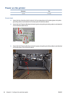
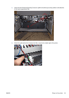
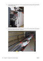
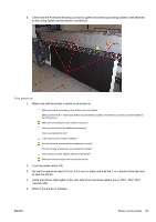
Also check the resistance between A2-B2, A2-C2, B2-C2 (marked on the static relay and on the heating and curing cables: 1, 2, 3). The acceptable values are as follows. ● Triangle configuration (low input tri-phase, 200-220 V between phases): resistance should be 8.3 Ω (min 7.7 Ω , Max : 9 Ohms) (calculation details: 2/3 * 12.5 Ω (minimum: 2/3 11.5 Ω , maximum: 2 / 3 13.5Ω). ● Star configuration (high input tri-phase, 380-415 V between phases): resistance should be 25 Ω (minimum: 23 Ω, maximum: 27 Ω). Check connections Check that the following items are correctly connected. ● The main interconnect ● The left remote controller board (remove the left trim) ● The ink supply module board ● The capping station's remote controller board ● The printhead cleaning roll station ● The tri-phase cables on the static relay: within the electrical cabinet, on the left, the two big black relays) The neutral or zero line of the tri-phase cables must not be connected. Connect mains power Manpower 1 person Time 5 minutes NOTE: This task must be performed by a certified electrician provided by the customer. NOTE: Make sure to route the power cables under the electrical cabinet structure. 1. Use the key to access the electrical cabinet. 2. Connect both power cables to the AC mains using the appropriate connectors or by wiring them directly to the PDU, according to the National Electrotechnical Code (NEC). For more information about the printer's electrical specifications, see the Site Preparation Guide. ENWW Check connections 31
-
 1
1 -
2
-
3
-
4
-
5
-
6
-
7
-
8
-
9
-
10
-
11
-
12
-
13
-
14
-
15
-
16
-
17
-
18
-
19
-
20
-
21
-
22
-
23
-
24
-
25
-
26
-
27
-
28
-
29
-
 30
30 -
 31
31 -
 32
32 -
 33
33 -
 34
34 -
 35
35 -
 36
36 -
 37
37 -
 38
38 -
 39
39 -
 40
40 -
41
-
42
-
43
-
44
-
45
-
46
-
47
-
48
-
49
-
50
-
51
-
52
-
53
-
54
-
55
-
56
-
57
-
58
-
59
-
60
-
61
-
62
-
63
-
64
-
65
-
66
-
67
-
68
-
69
-
70
-
71
-
72
-
73
-
74
-
75
-
76
-
77
-
78
-
79
-
80
-
81
-
82
-
83
-
84
-
85
 |
 |
