HP ML150 Optimizing facility operation in high density data center environment - Page 18
Rack geometry, Cooling footprint, Hot and cold aisle spacing, Row configuration
 |
UPC - 884420743644
View all HP ML150 manuals
Add to My Manuals
Save this manual to your list of manuals |
Page 18 highlights
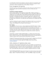
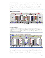
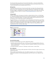
from 25 percent (the most common) to 56 percent (for high airflow). A 25 percent perforated tile provides approximately 500 cubic feet per minute (cfm) at a 5 percent static pressure drop, while a 56 percent perforated tile provides approximately 2000 cfm. Rack geometry Designing the data center layout to form hot and cold aisles is one step in the cooling optimization process. Also critical is the geometry of the rack layout. Research by HP Laboratories has revealed that minor changes in rack placement can change the fluid mechanics inside a data center and lead to inefficient utilization of CRAC units. See the "Thermal Assessment Services" section for more information. Cooling footprint The floor area that each rack requires must include an unobstructed area to draw in and discharge air. Almost all HP equipment cools from front to rear so that it can be placed in racks positioned sideby-side. The cooling footprint (Figure 13) includes width and depth of the rack plus the area in front for drawing in cool air and the area in back for exhausting hot air. Equipment that draws in air from the bottom or side or that exhausts air from the side or top will have a different cooling footprint. The total physical space required for the data center includes the cooling footprint of all the racks plus free space for aisles, ramps, and air distribution. Typically, a width of two floor tiles is needed in front of the rack, and a width of at least one unobstructed floor tile is needed behind the rack to facilitate cable routing. Figure 13. Cooling footprint Hot and cold aisle spacing The amount of space between rows of racks is determined as follows. • Cold aisle spacing should be 48 inches, two full tiles, and hot isle spacing should be at least one full tile, 24 inches minimum. This spacing is required for equipment installation and removal and for access beneath the floor. • Cold aisles should be a minimum of 14 feet apart, center-to-center, or seven full tiles. Row configuration Keep equipment rows as long as safety requirements will allow and avoid row gaps to prevent mixing of the hot and cold air. Where possible, locate high-density racks in the middle of equipment rows or mid-way between opposing air-conditioners. Avoid locating high-density racks at the ends of rows or deep into room corners. 18
-
 1
1 -
2
-
3
-
4
-
5
-
6
-
7
-
8
-
9
-
10
-
11
-
12
-
 13
13 -
 14
14 -
 15
15 -
 16
16 -
 17
17 -
 18
18 -
 19
19 -
 20
20 -
 21
21 -
 22
22 -
 23
23 -
24
-
25
-
26
 |
 |
