HP Mini 210-3001xx HP Mini 210, HP Mini 110, and Compaq Mini CQ10 Maintenance - Page 65
Release the TouchPad ZIF connector, Remove the two Phillips M2.0x5.0 screws
 |
View all HP Mini 210-3001xx manuals
Add to My Manuals
Save this manual to your list of manuals |
Page 65 highlights
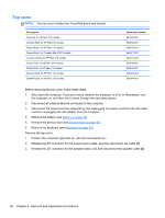
4. Remove the five Phillips M2.0x5.0 screws (3) from the top cover . 5. Position the computer upside down, with the front toward you. 6. Release the TouchPad ZIF connector (1) and disconnect the TouchPad cable (2). (The ZIF cable is secured with double-sided adhesive tape.) 7. Remove the five Phillips M2.0x5.0 screws (3) along the front edge of the base enclosure. 8. Remove the two Phillips M2.0x5.0 screws (4) from underneath the rear corner plates, one in each corner. Component replacement procedures 57
-
 1
1 -
2
-
3
-
4
-
5
-
6
-
7
-
8
-
9
-
10
-
11
-
12
-
13
-
14
-
15
-
16
-
17
-
18
-
19
-
20
-
21
-
22
-
23
-
24
-
25
-
26
-
27
-
28
-
29
-
30
-
31
-
32
-
33
-
34
-
35
-
36
-
37
-
38
-
39
-
40
-
41
-
42
-
43
-
44
-
45
-
46
-
47
-
48
-
49
-
50
-
51
-
52
-
53
-
54
-
55
-
56
-
57
-
58
-
59
-
 60
60 -
 61
61 -
 62
62 -
 63
63 -
 64
64 -
 65
65 -
 66
66 -
 67
67 -
 68
68 -
 69
69 -
 70
70 -
71
-
72
-
73
-
74
-
75
-
76
-
77
-
78
-
79
-
80
-
81
-
82
-
83
-
84
-
85
-
86
-
87
-
88
-
89
-
90
-
91
-
92
-
93
-
94
-
95
-
96
-
97
-
98
-
99
-
100
-
101
-
102
-
103
-
104
 |
 |

4.
Remove the five Phillips M2.0x5.0 screws
(3)
from the top cover .
5.
Position the computer upside down, with the front toward you.
6.
Release the TouchPad ZIF connector
(1)
and disconnect the TouchPad cable
(2)
. (The ZIF
cable is secured with double-sided adhesive tape.)
7.
Remove the five Phillips M2.0x5.0 screws
(3)
along the front edge of the base enclosure.
8.
Remove the two Phillips M2.0x5.0 screws
(4)
from underneath the rear corner plates, one in
each corner.
Component replacement procedures
57