HP Mini 210-3001xx HP Mini 210, HP Mini 110, and Compaq Mini CQ10 Maintenance - Page 76
WWAN module see, Memory module see
 |
View all HP Mini 210-3001xx manuals
Add to My Manuals
Save this manual to your list of manuals |
Page 76 highlights
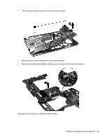
Description Intel Atom N475 single-core, 1.83 GHz processor, 512 KB level 2 cache, 667 MHz FSB, XSLOT (HP Mini 210 models) Intel Atom N570 dual-core 1.66 GHz processor, 1 MB level 2 cache, 667 MHz FSB Intel Atom N570 dual-core 1.66 GHz processor, 1 MB level 2 cache, 667 MHz FSB, XSLOT Spare part number 650741-001 650739-001 650742-001 Before removing the system board, follow these steps: 1. Shut down the computer. If you are unsure whether the computer is off or in Hibernation, turn the computer on, and then shut it down through the operating system. 2. Disconnect all external devices connected to the computer. 3. Disconnect the power from the computer by first unplugging the power cord from the AC outlet and then unplugging the AC adapter from the computer. 4. Remove the battery (see Battery on page 44). 5. Remove the service door (see Service door on page 45). 6. Disconnect the hard drive cable from the system board (see Hard drive on page 50). 7. Disconnect the WLAN antenna cables from the WLAN module (see WLAN module on page 46). 8. Disconnect the WWAN antenna cables from the WWAN module (see WWAN module on page 47). 9. Remove the keyboard (see Keyboard on page 53). 10. Remove the top cover (see Top cover on page 56). When replacing the system board, be sure that the following components are removed from the defective system board and installed on the replacement system board: ● WLAN module (see WLAN module on page 46) ● WWAN module (see WWAN module on page 47) ● Memory module (see Memory module on page 48) ● RTC battery (see RTC battery on page 49) Remove the system board: 1. Remove the 2 Phillips M2.0x5.0 screws (1) that secure the system board to the base enclosure . 2. Starting in the middle of the system board, lift the system board up, and then lift the right side of the system board (2) until it rests at an angle. 68 Chapter 4 Removal and replacement procedures
-
 1
1 -
2
-
3
-
4
-
5
-
6
-
7
-
8
-
9
-
10
-
11
-
12
-
13
-
14
-
15
-
16
-
17
-
18
-
19
-
20
-
21
-
22
-
23
-
24
-
25
-
26
-
27
-
28
-
29
-
30
-
31
-
32
-
33
-
34
-
35
-
36
-
37
-
38
-
39
-
40
-
41
-
42
-
43
-
44
-
45
-
46
-
47
-
48
-
49
-
50
-
51
-
52
-
53
-
54
-
55
-
56
-
57
-
58
-
59
-
60
-
61
-
62
-
63
-
64
-
65
-
66
-
67
-
68
-
69
-
70
-
 71
71 -
 72
72 -
 73
73 -
 74
74 -
 75
75 -
 76
76 -
 77
77 -
 78
78 -
 79
79 -
 80
80 -
 81
81 -
82
-
83
-
84
-
85
-
86
-
87
-
88
-
89
-
90
-
91
-
92
-
93
-
94
-
95
-
96
-
97
-
98
-
99
-
100
-
101
-
102
-
103
-
104
 |
 |
