HP Pavilion 13-s000 Pavilion x360 Convertible PC model numbers: 13-s000 throug - Page 40
Fan/heat sink assembly
 |
View all HP Pavilion 13-s000 manuals
Add to My Manuals
Save this manual to your list of manuals |
Page 40 highlights
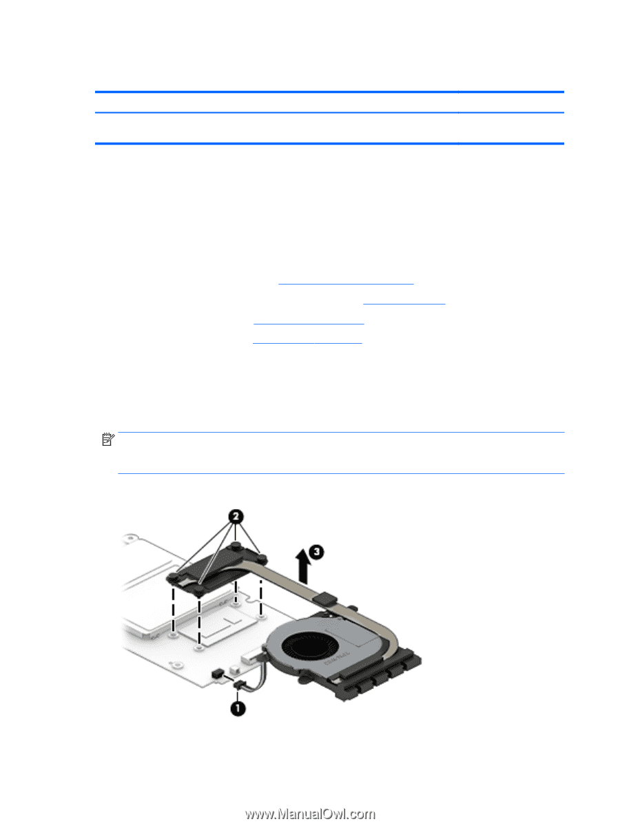
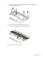
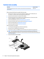
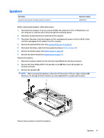
Fan/heat sink assembly Description Fan/heat sink assembly (includes fan cable, 4 captive screws [secured by C-clips], and replacement thermal material) Spare part number 809825-001 Before removing the fan/heat sink assembly, follow these steps: 1. Shut down the computer. If you are unsure whether the computer is off or in Hibernation, turn the computer on, and then shut it down through the operating system. 2. Disconnect all external devices connected to the computer. 3. Disconnect the power from the computer by first unplugging the power cord from the AC outlet and then unplugging the AC adapter from the computer. 4. Remove the keyboard/top cover (see Keyboard/top cover on page 22). 5. Disconnect the battery cable from the system board (see Battery on page 25). 6. Remove the WLAN module (see WLAN module on page 29). 7. Remove the system board (see System board on page 31). Remove the fan/heat sink assembly: 1. Turn the system board upside down with the front toward you. 2. Disconnect the fan cable (1) from the system board. 3. Loosen the four captive screws (2) that secure the fan/heat sink assembly to the system board. NOTE: Due to the adhesive quality of the thermal material located between the fan/heat sink assembly and system board components, it may be necessary to move the fan/heat sink assembly from side to side to detach it. 4. Remove the fan/heat sink assembly (3). 34 Chapter 5 Removal and replacement procedures
-
 1
1 -
2
-
3
-
4
-
5
-
6
-
7
-
8
-
9
-
10
-
11
-
12
-
13
-
14
-
15
-
16
-
17
-
18
-
19
-
20
-
21
-
22
-
23
-
24
-
25
-
26
-
27
-
28
-
29
-
30
-
31
-
32
-
33
-
34
-
 35
35 -
 36
36 -
 37
37 -
 38
38 -
 39
39 -
 40
40 -
 41
41 -
 42
42 -
 43
43 -
 44
44 -
 45
45 -
46
-
47
-
48
-
49
-
50
-
51
-
52
-
53
-
54
-
55
-
56
-
57
-
58
-
59
-
60
-
61
-
62
-
63
-
64
-
65
-
66
-
67
-
68
-
69
-
70
 |
 |