HP Pavilion 15-cd000 Maintenance and Service Guide - Page 48
Remove the Phillips PM2.0×2.3 screw, by pulling the module away from the slot at an angle.
 |
View all HP Pavilion 15-cd000 manuals
Add to My Manuals
Save this manual to your list of manuals |
Page 48 highlights
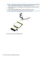
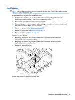
NOTE: The WLAN antenna cable labeled "1/MAIN" connects to the WLAN module "Main" terminal. The WLAN antenna cable labeled "2/AUX" connects to the WLAN module "Aux" terminal. 2. Remove the Phillips PM2.0×2.3 screw (2) that secures the WLAN module to the computer. (The WLAN module tilts up.) 3. Remove the WLAN module (3) by pulling the module away from the slot at an angle. NOTE: WLAN modules are designed with a notch to prevent incorrect insertion. Reverse this procedure to install the WLAN module. 40 Chapter 5 Removal and replacement procedures
-
 1
1 -
2
-
3
-
4
-
5
-
6
-
7
-
8
-
9
-
10
-
11
-
12
-
13
-
14
-
15
-
16
-
17
-
18
-
19
-
20
-
21
-
22
-
23
-
24
-
25
-
26
-
27
-
28
-
29
-
30
-
31
-
32
-
33
-
34
-
35
-
36
-
37
-
38
-
39
-
40
-
41
-
42
-
 43
43 -
 44
44 -
 45
45 -
 46
46 -
 47
47 -
 48
48 -
 49
49 -
 50
50 -
 51
51 -
 52
52 -
 53
53 -
54
-
55
-
56
-
57
-
58
-
59
-
60
-
61
-
62
-
63
-
64
-
65
-
66
-
67
-
68
-
69
-
70
-
71
-
72
-
73
-
74
-
75
-
76
-
77
-
78
-
79
-
80
-
81
-
82
-
83
-
84
-
85
-
86
-
87
-
88
-
89
-
90
-
91
-
92
-
93
-
94
-
95
-
96
-
97
-
98
 |
 |

NOTE:
The WLAN antenna cable labeled "1/MAIN" connects to the WLAN module "Main" terminal. The
WLAN antenna cable labeled "2/AUX" connects to the WLAN module "Aux" terminal.
2.
Remove the Phillips PM2.0×2.3 screw
(2)
that secures the WLAN module to the computer. (The WLAN
module tilts up.)
3.
Remove the WLAN module
(3)
by pulling the module away from the slot at an angle.
NOTE:
WLAN modules are designed with a notch to prevent incorrect insertion.
Reverse this procedure to install the WLAN module.
40
Chapter 5
Removal and replacement procedures