HP Pavilion 15-cd000 Maintenance and Service Guide - Page 51
USB port board, Disconnect the power from the computer
 |
View all HP Pavilion 15-cd000 manuals
Add to My Manuals
Save this manual to your list of manuals |
Page 51 highlights
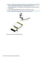
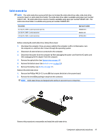
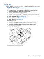
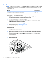
2. Remove the memory module (2) by pulling the module away from the slot at an angle. NOTE: Memory modules are designed with a notch to prevent incorrect insertion. Reverse this procedure to install a memory module. USB port board NOTE: The USB port board spare part kit does not include the USB port board cable. The USB port board cable is available using spare part numbers 926842-001. Description Spare part number For use only on computer models equipped with an Intel Dual Band Wireless-AC 7265 802.11 AC 2×2 WiFi + Bluetooth 4.2 Combo Adapter (non-vPro; includes power light actuator, hard drive light actuator, card reader slot, and USB port) 926899-001 For use only on computer models equipped with an Intel Dual Band Wireless-AC 3168 802.11AC 1×1 WiFi 926854-001 + Bluetooth 4.2 Combo Adapter (non-vPro) or a Realtek RTL8723DE 802.11 bgn 1×1 WiFi + Bluetooth 4.2 Combo Adapter (includes power light actuator, hard drive light actuator, card reader slot, and USB port) Before removing the USB port board, follow these steps: 1. Shut down the computer. If you are unsure whether the computer is off or in Hibernation, turn the computer on, and then shut it down through the operating system. 2. Disconnect all external devices connected to the computer. 3. Disconnect the power from the computer by first unplugging the power cord from the AC outlet, and then unplugging the AC adapter from the computer. 4. Remove the optical drive (see Optical drive on page 34). 5. Remove the bottom cover (see Bottom cover on page 35). 6. Remove the battery (see Battery on page 37). Component replacement procedures 43
-
 1
1 -
2
-
3
-
4
-
5
-
6
-
7
-
8
-
9
-
10
-
11
-
12
-
13
-
14
-
15
-
16
-
17
-
18
-
19
-
20
-
21
-
22
-
23
-
24
-
25
-
26
-
27
-
28
-
29
-
30
-
31
-
32
-
33
-
34
-
35
-
36
-
37
-
38
-
39
-
40
-
41
-
42
-
43
-
44
-
45
-
 46
46 -
 47
47 -
 48
48 -
 49
49 -
 50
50 -
 51
51 -
 52
52 -
 53
53 -
 54
54 -
 55
55 -
 56
56 -
57
-
58
-
59
-
60
-
61
-
62
-
63
-
64
-
65
-
66
-
67
-
68
-
69
-
70
-
71
-
72
-
73
-
74
-
75
-
76
-
77
-
78
-
79
-
80
-
81
-
82
-
83
-
84
-
85
-
86
-
87
-
88
-
89
-
90
-
91
-
92
-
93
-
94
-
95
-
96
-
97
-
98
 |
 |
