HP Pavilion 15-cd000 Maintenance and Service Guide - Page 57
Memory module see, Heat sink see
 |
View all HP Pavilion 15-cd000 manuals
Add to My Manuals
Save this manual to your list of manuals |
Page 57 highlights
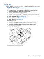
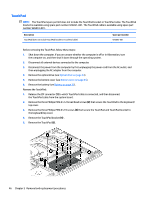
Description Equipped with an AMD A9-9420P 3.00-GHz (turbo up to 3.60-GHz) dual core processor (1866-MHz FSB, 1.0-GB L2 cache, 15-W), an AMD Radeon R5 UMA graphics subsystem, hard drive and solid-state drive connectors, and a non-Windows operating system Equipped with an AMD A6-9220P 2.50-GHz (turbo up to 2.90-GHz) dual core processor (1866-MHz FSB, 1.0-GB L2 cache, 15-W), an AMD Radeon R4 UMA graphics subsystem, and the Windows 10 operating system Equipped with an AMD A6-9220P 2.50-GHz (turbo up to 2.90-GHz) dual core processor (1866-MHz FSB, 1.0-GB L2 cache, 15-W), an AMD Radeon R4 UMA graphics subsystem, and a non-Windows operating system Spare part number 926284-001 926285-601 926285-001 Before removing the system board, follow these steps: 1. Shut down the computer. If you are unsure whether the computer is off or in Hibernation, turn the computer on, and then shut it down through the operating system. 2. Disconnect all external devices connected to the computer. 3. Disconnect the power from the computer by first unplugging the power cord from the AC outlet, and then unplugging the AC adapter from the computer. 4. Remove the optical drive (see Optical drive on page 34), and then remove the following components: a. Bottom cover (see Bottom cover on page 35) b. Battery (see Battery on page 37) c. Hard drive (see Hard drive on page 38) d. Solid-state drive (see Solid-state drive on page 41) e. Fan (see Fan on page 47) When replacing the system board, be sure to remove the following components from the defective system board and install them on the replacement system board: ● WLAN module (see WLAN module on page 39) ● Memory module (see Memory module on page 42) ● Heat sink (see Heat sink on page 52) ● USB port board cable (see USB port board cable on page 55) Remove the system board: 1. Disconnect the following cables from the system board: (1) Power connector cable (2) WLAN antenna cables NOTE: The #1/white WLAN antenna cable connects to the WLAN module "#1/Main" terminal. The #2/ black WLAN antenna cable connects to the WLAN module "#2/Aux" terminal. (3) Display panel ZIF connector cable (4) Speaker cable (5) TouchPad ZIF connector cable Component replacement procedures 49
-
 1
1 -
2
-
3
-
4
-
5
-
6
-
7
-
8
-
9
-
10
-
11
-
12
-
13
-
14
-
15
-
16
-
17
-
18
-
19
-
20
-
21
-
22
-
23
-
24
-
25
-
26
-
27
-
28
-
29
-
30
-
31
-
32
-
33
-
34
-
35
-
36
-
37
-
38
-
39
-
40
-
41
-
42
-
43
-
44
-
45
-
46
-
47
-
48
-
49
-
50
-
51
-
 52
52 -
 53
53 -
 54
54 -
 55
55 -
 56
56 -
 57
57 -
 58
58 -
 59
59 -
 60
60 -
 61
61 -
 62
62 -
63
-
64
-
65
-
66
-
67
-
68
-
69
-
70
-
71
-
72
-
73
-
74
-
75
-
76
-
77
-
78
-
79
-
80
-
81
-
82
-
83
-
84
-
85
-
86
-
87
-
88
-
89
-
90
-
91
-
92
-
93
-
94
-
95
-
96
-
97
-
98
 |
 |
