HP Pavilion 17-f000 Maintenance and Service Guide - Page 101
on the left and one broadhead screw, Remove the six Phillips screws
 |
View all HP Pavilion 17-f000 manuals
Add to My Manuals
Save this manual to your list of manuals |
Page 101 highlights
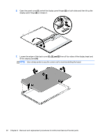
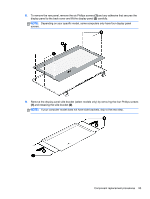
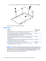
4. Remove the power connector cover by removing the Phillips screw (1) and lifting the cover (2). NOTE: The power connector cover has two screws, however, the screw on the left is removed during the base enclosure and top cover removal process. Removing the cover is required for the display panel removal. NOTE: You will remove the power connector after you have removed the system board. This procedure is to remove the power connector cover. 5. Remove the six Phillips screws (1) on the left and one broadhead screw (2) on the right side base of the display panel. Lift the panel up (3). NOTE: Support the display panel as you are removing the screws. Component replacement procedures 91
-
 1
1 -
2
-
3
-
4
-
5
-
6
-
7
-
8
-
9
-
10
-
11
-
12
-
13
-
14
-
15
-
16
-
17
-
18
-
19
-
20
-
21
-
22
-
23
-
24
-
25
-
26
-
27
-
28
-
29
-
30
-
31
-
32
-
33
-
34
-
35
-
36
-
37
-
38
-
39
-
40
-
41
-
42
-
43
-
44
-
45
-
46
-
47
-
48
-
49
-
50
-
51
-
52
-
53
-
54
-
55
-
56
-
57
-
58
-
59
-
60
-
61
-
62
-
63
-
64
-
65
-
66
-
67
-
68
-
69
-
70
-
71
-
72
-
73
-
74
-
75
-
76
-
77
-
78
-
79
-
80
-
81
-
82
-
83
-
84
-
85
-
86
-
87
-
88
-
89
-
90
-
91
-
92
-
93
-
94
-
95
-
 96
96 -
 97
97 -
 98
98 -
 99
99 -
 100
100 -
 101
101 -
 102
102 -
 103
103 -
 104
104 -
 105
105 -
 106
106 -
107
-
108
-
109
-
110
-
111
-
112
-
113
-
114
-
115
-
116
-
117
-
118
-
119
-
120
-
121
-
122
-
123
-
124
-
125
-
126
-
127
-
128
-
129
-
130
-
131
-
132
-
133
-
134
-
135
-
136
-
137
-
138
-
139
-
140
-
141
-
142
-
143
-
144
-
145
-
146
-
147
-
148
-
149
-
150
-
151
-
152
-
153
-
154
-
155
-
156
-
157
-
158
-
159
-
160
-
161
-
162
-
163
-
164
-
165
-
166
 |
 |

4.
Remove the power connector cover by removing the Phillips screw
(1)
and lifting the cover
(2)
.
NOTE:
The power connector cover has two screws, however, the screw on the left is removed
during the base enclosure and top cover removal process. Removing the cover is required for
the display panel removal.
NOTE:
You will remove the power connector after you have removed the system board. This
procedure is to remove the power connector cover.
5.
Remove the six Phillips screws
(1)
on the left and one broadhead screw
(2)
on the right side
base of the display panel. Lift the panel up
(3)
.
NOTE:
Support the display panel as you are removing the screws.
Component replacement procedures
91