HP Pavilion 17-f000 Maintenance and Service Guide - Page 96
Keyboard cable, Carefully disconnect the following cables
 |
View all HP Pavilion 17-f000 manuals
Add to My Manuals
Save this manual to your list of manuals |
Page 96 highlights
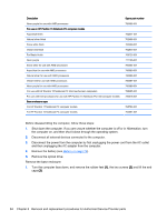
3. Remove five screws (1) around the battery area, three broadhead screws (2) in the optical drive bay and one screw (3) near the display hinge. NOTE: Some models may have two screws in the optical drive bay (2). 4. Turn the computer right side up and carefully remove the top cover. NOTE: Use a thin, non-conductive tool to lift the top cover.. 5. Carefully disconnect the following cables: ● Power button cable (1) ● Keyboard cable (2) ● TouchPad cable (3) Lift the top cover (4) to remove it from the computer. 86 Chapter 6 Removal and replacement procedures for Authorized Service Provider parts
-
 1
1 -
2
-
3
-
4
-
5
-
6
-
7
-
8
-
9
-
10
-
11
-
12
-
13
-
14
-
15
-
16
-
17
-
18
-
19
-
20
-
21
-
22
-
23
-
24
-
25
-
26
-
27
-
28
-
29
-
30
-
31
-
32
-
33
-
34
-
35
-
36
-
37
-
38
-
39
-
40
-
41
-
42
-
43
-
44
-
45
-
46
-
47
-
48
-
49
-
50
-
51
-
52
-
53
-
54
-
55
-
56
-
57
-
58
-
59
-
60
-
61
-
62
-
63
-
64
-
65
-
66
-
67
-
68
-
69
-
70
-
71
-
72
-
73
-
74
-
75
-
76
-
77
-
78
-
79
-
80
-
81
-
82
-
83
-
84
-
85
-
86
-
87
-
88
-
89
-
90
-
 91
91 -
 92
92 -
 93
93 -
 94
94 -
 95
95 -
 96
96 -
 97
97 -
 98
98 -
 99
99 -
 100
100 -
 101
101 -
102
-
103
-
104
-
105
-
106
-
107
-
108
-
109
-
110
-
111
-
112
-
113
-
114
-
115
-
116
-
117
-
118
-
119
-
120
-
121
-
122
-
123
-
124
-
125
-
126
-
127
-
128
-
129
-
130
-
131
-
132
-
133
-
134
-
135
-
136
-
137
-
138
-
139
-
140
-
141
-
142
-
143
-
144
-
145
-
146
-
147
-
148
-
149
-
150
-
151
-
152
-
153
-
154
-
155
-
156
-
157
-
158
-
159
-
160
-
161
-
162
-
163
-
164
-
165
-
166
 |
 |

3.
Remove five screws
(1)
around the battery area, three broadhead screws
(2)
in the optical drive
bay and one screw
(3)
near the display hinge.
NOTE:
Some models may have two screws in the optical drive bay
(2)
.
4.
Turn the computer right side up and carefully remove the top cover.
NOTE:
Use a thin, non-conductive tool to lift the top cover..
5.
Carefully disconnect the following cables:
●
Power button cable
(1)
●
Keyboard cable
(2)
●
TouchPad cable
(3)
Lift the top cover
(4)
to remove it from the computer.
86
Chapter 6
Removal and replacement procedures for Authorized Service Provider parts