HP Pavilion 17-f000 Maintenance and Service Guide - Page 107
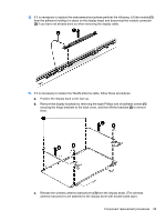
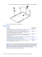
Remove the Phillips PM screws, The WLAN module may have two screws depending on the model.
 |
View all HP Pavilion 17-f000 manuals
Add to My Manuals
Save this manual to your list of manuals |
Page 107 highlights
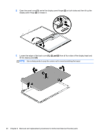
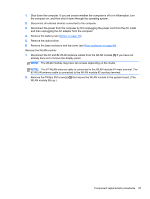
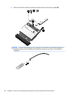
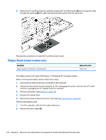
1. Shut down the computer. If you are unsure whether the computer is off or in Hibernation, turn the computer on, and then shut it down through the operating system. 2. Disconnect all external devices connected to the computer. 3. Disconnect the power from the computer by first unplugging the power cord from the AC outlet and then unplugging the AC adapter from the computer. 4. Remove the battery (see Battery on page 76). 5. Remove the optical drive. 6. Remove the base enclosure and top cover (see Base enclosure on page 80). Remove the WLAN module: 1. Disconnect the #1 and #2 WLAN antenna cables from the WLAN module (1) if you have not already done so to remove the display panel.. NOTE: The WLAN module may have two screws depending on the model. NOTE: The #1 WLAN antenna cable is connected to the WLAN module #1 main terminal. The #2 WLAN antenna cable is connected to the WLAN module #2 auxiliary terminal. 2. Remove the Phillips PM screw(s) (2) that secure the WLAN module to the system board. (The WLAN module tilts up.) Component replacement procedures 97
-
 1
1 -
2
-
3
-
4
-
5
-
6
-
7
-
8
-
9
-
10
-
11
-
12
-
13
-
14
-
15
-
16
-
17
-
18
-
19
-
20
-
21
-
22
-
23
-
24
-
25
-
26
-
27
-
28
-
29
-
30
-
31
-
32
-
33
-
34
-
35
-
36
-
37
-
38
-
39
-
40
-
41
-
42
-
43
-
44
-
45
-
46
-
47
-
48
-
49
-
50
-
51
-
52
-
53
-
54
-
55
-
56
-
57
-
58
-
59
-
60
-
61
-
62
-
63
-
64
-
65
-
66
-
67
-
68
-
69
-
70
-
71
-
72
-
73
-
74
-
75
-
76
-
77
-
78
-
79
-
80
-
81
-
82
-
83
-
84
-
85
-
86
-
87
-
88
-
89
-
90
-
91
-
92
-
93
-
94
-
95
-
96
-
97
-
98
-
99
-
100
-
101
-
 102
102 -
 103
103 -
 104
104 -
 105
105 -
 106
106 -
 107
107 -
 108
108 -
 109
109 -
 110
110 -
 111
111 -
 112
112 -
113
-
114
-
115
-
116
-
117
-
118
-
119
-
120
-
121
-
122
-
123
-
124
-
125
-
126
-
127
-
128
-
129
-
130
-
131
-
132
-
133
-
134
-
135
-
136
-
137
-
138
-
139
-
140
-
141
-
142
-
143
-
144
-
145
-
146
-
147
-
148
-
149
-
150
-
151
-
152
-
153
-
154
-
155
-
156
-
157
-
158
-
159
-
160
-
161
-
162
-
163
-
164
-
165
-
166
 |
 |
