HP Pavilion dm1-4300 HP Pavilion dm1 Entertainment PC Maintenance and Service - Page 76
Memory module see, RTC battery see
 |
View all HP Pavilion dm1-4300 manuals
Add to My Manuals
Save this manual to your list of manuals |
Page 76 highlights
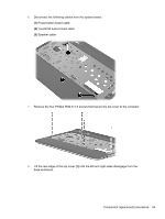
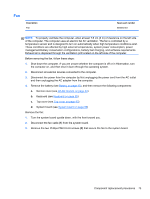
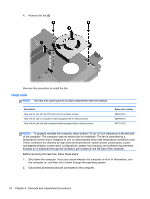
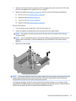
3. Disconnect the power from the computer by first unplugging the power cord from the AC outlet and then unplugging the AC adapter from the computer. 4. Remove the battery (see Battery on page 40). 5. Remove the WLAN module (see WLAN module on page 44). 6. Remove the WWAN module (see WWAN module (select models only) on page 47). 7. Disconnect the hard drive connector cable from the system board (see Hard drive on page 51). 8. Remove the keyboard (see Keyboard on page 55). 9. Disconnect the display panel cable from the system board (see Display assembly on page 58). 10. Remove the top cover (see Top cover on page 63). When replacing the system board, be sure that the following components are removed from the defective system board and installed on the replacement system board: ● SIM (see SIM (select models only) on page 41) ● RTC battery (see RTC battery on page 49) ● Memory module (see Memory module on page 53) ● Power connector cable (see Power connector cable on page 71) ● Fan (see Fan on page 73) ● Heat sink (see Heat sink on page 74) Remove the system board: 1. Lift the left side of the system board (1) until it rests at an angle. 70 Chapter 4 Removal and replacement procedures
-
 1
1 -
2
-
3
-
4
-
5
-
6
-
7
-
8
-
9
-
10
-
11
-
12
-
13
-
14
-
15
-
16
-
17
-
18
-
19
-
20
-
21
-
22
-
23
-
24
-
25
-
26
-
27
-
28
-
29
-
30
-
31
-
32
-
33
-
34
-
35
-
36
-
37
-
38
-
39
-
40
-
41
-
42
-
43
-
44
-
45
-
46
-
47
-
48
-
49
-
50
-
51
-
52
-
53
-
54
-
55
-
56
-
57
-
58
-
59
-
60
-
61
-
62
-
63
-
64
-
65
-
66
-
67
-
68
-
69
-
70
-
 71
71 -
 72
72 -
 73
73 -
 74
74 -
 75
75 -
 76
76 -
 77
77 -
 78
78 -
 79
79 -
 80
80 -
 81
81 -
82
-
83
-
84
-
85
-
86
-
87
-
88
-
89
-
90
-
91
-
92
-
93
-
94
-
95
-
96
-
97
-
98
-
99
-
100
-
101
-
102
-
103
-
104
-
105
-
106
-
107
-
108
-
109
-
110
-
111
 |
 |
