HP Pavilion dm1-4300 HP Pavilion dm1 Entertainment PC Maintenance and Service - Page 81
The thermal material must be thoroughly cleaned from the surfaces of the heat sink and
 |
View all HP Pavilion dm1-4300 manuals
Add to My Manuals
Save this manual to your list of manuals |
Page 81 highlights
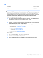
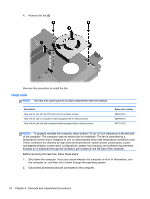
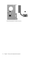
3. Disconnect the power from the computer by first unplugging the power cord from the AC outlet and then unplugging the AC adapter from the computer. 4. Remove the battery (see Battery on page 40), and then remove the following components: a. Service cover (see WLAN module on page 44) b. Keyboard (see Keyboard on page 55) c. Top cover (see Top cover on page 63) d. System board (see System board on page 69) Remove the heat sink: 1. Turn the system board upside down, with the front toward you. 2. Loosen the captive screws (1) that secure the heat sink to the system board. NOTE: The number of screws used to secure the heat sink to the system board varies by computer model. NOTE: Due to the adhesive quality of the thermal material located between the heat sink and system board components, it may be necessary to move the heat sink from side to side to detach it. 3. Remove the heat sink (2). NOTE: The thermal material must be thoroughly cleaned from the surfaces of the heat sink and the system board components each time the heat sink is removed. Replacement thermal material is included with the heat sink and system board spare part kits. The following illustration shows the replacement thermal material locations on a computer model equipped with an AMD processor and a graphics subsystem with discrete memory. Thermal paste is used on the processor (1) and the heat sink section (2) that services it. Component replacement procedures 75
-
 1
1 -
2
-
3
-
4
-
5
-
6
-
7
-
8
-
9
-
10
-
11
-
12
-
13
-
14
-
15
-
16
-
17
-
18
-
19
-
20
-
21
-
22
-
23
-
24
-
25
-
26
-
27
-
28
-
29
-
30
-
31
-
32
-
33
-
34
-
35
-
36
-
37
-
38
-
39
-
40
-
41
-
42
-
43
-
44
-
45
-
46
-
47
-
48
-
49
-
50
-
51
-
52
-
53
-
54
-
55
-
56
-
57
-
58
-
59
-
60
-
61
-
62
-
63
-
64
-
65
-
66
-
67
-
68
-
69
-
70
-
71
-
72
-
73
-
74
-
75
-
 76
76 -
 77
77 -
 78
78 -
 79
79 -
 80
80 -
 81
81 -
 82
82 -
 83
83 -
 84
84 -
 85
85 -
 86
86 -
87
-
88
-
89
-
90
-
91
-
92
-
93
-
94
-
95
-
96
-
97
-
98
-
99
-
100
-
101
-
102
-
103
-
104
-
105
-
106
-
107
-
108
-
109
-
110
-
111
 |
 |
