HP Pavilion dm1-4400 HP Pavilion dm1 Entertainment PC Maintenance and Service - Page 49
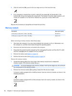
Remove the Phillips PM2.0×3.7 screw, CAUTION
 |
View all HP Pavilion dm1-4400 manuals
Add to My Manuals
Save this manual to your list of manuals |
Page 49 highlights
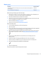
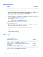
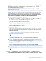
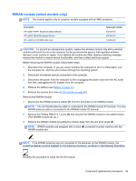
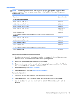
Description Broadcom 802.11 2×2 b/g/n wireless LAN + Bluetooth (BT 4.0 + HS support) combo (for use only with computer models equipped with an Intel processor) 802.11 b/g/n 1×2 Intel Centrino Wireless-N 1030 + Bluetooth combo (for use only with computer models equipped with an Intel processor) Spare part number 636672-001 631956-001 CAUTION: To prevent an unresponsive system, replace the wireless module only with a wireless module authorized for use in the computer by the governmental agency that regulates wireless devices in your country or region. If you replace the module and then receive a warning message, remove the module to restore device functionality, and then contact technical support. Before removing the WLAN module, follow these steps: 1. Shut down the computer. If you are unsure whether the computer is off or in Hibernation, turn the computer on, and then shut it down through the operating system. 2. Disconnect all external devices connected to the computer. 3. Disconnect the power from the computer by first unplugging the power cord from the AC outlet and then unplugging the AC adapter from the computer. 4. Remove the battery (see Battery on page 37). Remove the WLAN module: 1. With one hand, slide the battery/service door latch (1) to release the service door, and at the same time, use the other hand to press down on the service door, and then slide it toward the front of the computer (2). 2. Lift the door to remove it (3).The service door is available. For spare part numbers, see Computer major components on page 17. 3. Disconnect the WLAN antenna cables (1) from the terminals on the WLAN module. NOTE: The #1 WLAN antenna cable is connected to the WLAN module #1 terminal. The #2 WLAN antenna cable is connected to the WLAN module #2 terminal. 4. Remove the Phillips PM2.0×3.7 screw (2) that secures the WLAN module to the system board. (The WLAN module tilts up.) 5. Remove the WLAN module by pulling the module away from the slot at an angle (3). NOTE: WLAN modules are designed with a notch (4) to prevent incorrect insertion into the memory module slot. NOTE: If the WLAN antennas are not connected to the terminals on the WLAN module, the protective sleeves must be installed on the antenna connectors, as shown in the following illustration. Component replacement procedures 41
-
 1
1 -
2
-
3
-
4
-
5
-
6
-
7
-
8
-
9
-
10
-
11
-
12
-
13
-
14
-
15
-
16
-
17
-
18
-
19
-
20
-
21
-
22
-
23
-
24
-
25
-
26
-
27
-
28
-
29
-
30
-
31
-
32
-
33
-
34
-
35
-
36
-
37
-
38
-
39
-
40
-
41
-
42
-
43
-
 44
44 -
 45
45 -
 46
46 -
 47
47 -
 48
48 -
 49
49 -
 50
50 -
 51
51 -
 52
52 -
 53
53 -
 54
54 -
55
-
56
-
57
-
58
-
59
-
60
-
61
-
62
-
63
-
64
-
65
-
66
-
67
-
68
-
69
-
70
-
71
-
72
-
73
-
74
-
75
-
76
-
77
-
78
-
79
-
80
-
81
-
82
-
83
-
84
-
85
-
86
-
87
-
88
-
89
-
90
-
91
-
92
-
93
-
94
-
95
-
96
-
97
-
98
 |
 |