HP Pavilion dm1-4400 HP Pavilion dm1 Entertainment PC Maintenance and Service - Page 57
Display assembly, Remove the rear covers see
 |
View all HP Pavilion dm1-4400 manuals
Add to My Manuals
Save this manual to your list of manuals |
Page 57 highlights
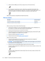
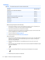
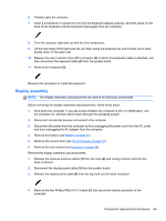
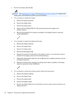
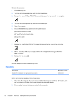
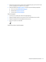
6. Partially open the computer. 7. Insert a screwdriver or similar thin tool into the keyboard release opening, and then press on the back of the keyboard until the keyboard disengages from the computer. 8. Turn the computer right-side up with the front toward you. 9. Lift the rear edge of the keyboard (1), and then swing the keyboard up and forward until it rests upside down on the palm rest. 10. Release the zero insertion force (ZIF) connector (2) to which the keyboard cable is attached, and then disconnect the keyboard cable (3) from the system board. 11. Remove the keyboard (3). Reverse this procedure to install the keyboard. Display assembly NOTE: The display assembly subcomponents are spared as individual components. Before removing the display assembly subcomponents, follow these steps: 1. Shut down the computer. If you are unsure whether the computer is off or in Hibernation, turn the computer on, and then shut it down through the operating system. 2. Disconnect all external devices connected to the computer. 3. Disconnect the power from the computer by first unplugging the power cord from the AC outlet and then unplugging the AC adapter from the computer. 4. Remove the battery (see Battery on page 37). 5. Remove the service door (see WLAN module on page 40). 6. Remove the rear covers (see Keyboard on page 48). Remove the display assembly subcomponents: 1. Release the wireless antenna cables (1) from the clips (2) and routing channel built into the base enclosure. 2. Disconnect the display panel cable (3) from the system board. 3. Release the display panel cable (4) from the clip built into the base enclosure. 4. Remove the two Phillips PM2.0×5.7 screws (1) that secure the display assembly to the computer. Component replacement procedures 49
-
 1
1 -
2
-
3
-
4
-
5
-
6
-
7
-
8
-
9
-
10
-
11
-
12
-
13
-
14
-
15
-
16
-
17
-
18
-
19
-
20
-
21
-
22
-
23
-
24
-
25
-
26
-
27
-
28
-
29
-
30
-
31
-
32
-
33
-
34
-
35
-
36
-
37
-
38
-
39
-
40
-
41
-
42
-
43
-
44
-
45
-
46
-
47
-
48
-
49
-
50
-
51
-
 52
52 -
 53
53 -
 54
54 -
 55
55 -
 56
56 -
 57
57 -
 58
58 -
 59
59 -
 60
60 -
 61
61 -
 62
62 -
63
-
64
-
65
-
66
-
67
-
68
-
69
-
70
-
71
-
72
-
73
-
74
-
75
-
76
-
77
-
78
-
79
-
80
-
81
-
82
-
83
-
84
-
85
-
86
-
87
-
88
-
89
-
90
-
91
-
92
-
93
-
94
-
95
-
96
-
97
-
98
 |
 |