HP Pavilion dm1-4400 HP Pavilion dm1 Entertainment PC Maintenance and Service - Page 67
computer model., Due to the adhesive quality of the thermal material located between the heat sink
 |
View all HP Pavilion dm1-4400 manuals
Add to My Manuals
Save this manual to your list of manuals |
Page 67 highlights
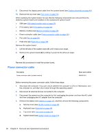
Description Heat sink for use on computer models equipped with an AMD processor Heat sink for use only with computer models equipped with an Intel processor Spare part number 664999-001 667121-001 NOTE: To properly ventilate the computer, allow at least 7.6 cm (3 in) of clearance on the left side of the computer. The computer uses an electric fan for ventilation. The fan is controlled by a temperature sensor and is designed to turn on automatically when high temperature conditions exist. These conditions are affected by high external temperatures, system power consumption, power management/battery conservation configurations, battery fast charging, and software requirements. Exhaust air is displaced through the ventilation grill located on the left side of the computer. Before removing the heat sink, follow these steps: 1. Shut down the computer. If you are unsure whether the computer is off or in Hibernation, turn the computer on, and then shut it down through the operating system. 2. Disconnect all external devices connected to the computer. 3. Disconnect the power from the computer by first unplugging the power cord from the AC outlet and then unplugging the AC adapter from the computer. 4. Remove the battery (see Battery on page 37), and then remove the following components: a. Service cover (see WLAN module on page 40) b. Keyboard (see Keyboard on page 48) c. Top cover (see Top cover on page 51) d. System board (see System board on page 54) Remove the heat sink: 1. Turn the system board upside down, with the front toward you. 2. Loosen the captive screws (1) that secure the heat sink to the system board. NOTE: The number of screws used to secure the heat sink to the system board varies by computer model. NOTE: Due to the adhesive quality of the thermal material located between the heat sink and system board components, it may be necessary to move the heat sink from side to side to detach it. 3. Remove the heat sink (2). NOTE: The thermal material must be thoroughly cleaned from the surfaces of the heat sink and the system board components each time the heat sink is removed. Replacement thermal material is included with the heat sink and system board spare part kits. The following illustration shows the replacement thermal material locations on a computer model equipped with an AMD processor and a graphics subsystem with discrete memory. Thermal paste is used on the processor (1) and the heat sink section (2) that services it. Component replacement procedures 59
-
 1
1 -
2
-
3
-
4
-
5
-
6
-
7
-
8
-
9
-
10
-
11
-
12
-
13
-
14
-
15
-
16
-
17
-
18
-
19
-
20
-
21
-
22
-
23
-
24
-
25
-
26
-
27
-
28
-
29
-
30
-
31
-
32
-
33
-
34
-
35
-
36
-
37
-
38
-
39
-
40
-
41
-
42
-
43
-
44
-
45
-
46
-
47
-
48
-
49
-
50
-
51
-
52
-
53
-
54
-
55
-
56
-
57
-
58
-
59
-
60
-
61
-
 62
62 -
 63
63 -
 64
64 -
 65
65 -
 66
66 -
 67
67 -
 68
68 -
 69
69 -
 70
70 -
 71
71 -
 72
72 -
73
-
74
-
75
-
76
-
77
-
78
-
79
-
80
-
81
-
82
-
83
-
84
-
85
-
86
-
87
-
88
-
89
-
90
-
91
-
92
-
93
-
94
-
95
-
96
-
97
-
98
 |
 |