HP Pavilion dm1-4400 HP Pavilion dm1 Entertainment PC Maintenance and Service - Page 58
Remove the four Phillips PM2.0×4.2, Remove the Phillips PM2.0×4.2 screw
 |
View all HP Pavilion dm1-4400 manuals
Add to My Manuals
Save this manual to your list of manuals |
Page 58 highlights
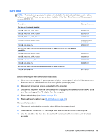
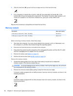
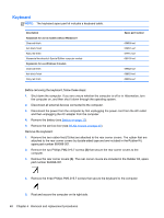
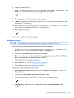
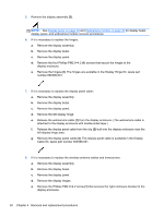
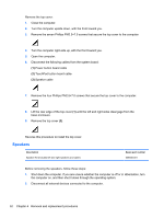
5. Remove the display assembly (2). NOTE: See Display panel on page 39 and Webcamera module on page 40 for display bezel, display panel, and webcamera module removal procedures. 6. If it is necessary to replace the hinges: a. Remove the display assembly. b. Remove the display bezel. c. Remove the display panel. d. Remove the four Phillips PM2.0×4.2 (1) screws that secure the hinges to the display enclosure. e. Remove the hinges (2). The hinges are available in the Display Hinge Kit, spare part number 659499-001. 7. If it is necessary to replace the display panel cable: a. Remove the display assembly. b. Remove the display bezel. c. Remove the display panel. d. Remove the left display hinge. e. Release the webcamera cable (1) from the display enclosure. (The webcamera cable is attached to the display enclosure with double-sided tape.) f. Release the display panel cable from the clip (2) built into the display enclosure near the left display hinge area. g. Remove the display panel cable (3). The display panel cable is available in the Display Cable Kit, spare part number 659498-001. 8. If it is necessary to replace the wireless antenna cables and transceivers: a. Remove the display assembly. b. Remove the display bezel. c. Remove the display panel. d. Remove the display hinges. e. Remove the Phillips PM2.0×4.2 screw (1) that secures the right enclosure bracket to the display enclosure. 50 Chapter 4 Removal and replacement procedures
-
 1
1 -
2
-
3
-
4
-
5
-
6
-
7
-
8
-
9
-
10
-
11
-
12
-
13
-
14
-
15
-
16
-
17
-
18
-
19
-
20
-
21
-
22
-
23
-
24
-
25
-
26
-
27
-
28
-
29
-
30
-
31
-
32
-
33
-
34
-
35
-
36
-
37
-
38
-
39
-
40
-
41
-
42
-
43
-
44
-
45
-
46
-
47
-
48
-
49
-
50
-
51
-
52
-
 53
53 -
 54
54 -
 55
55 -
 56
56 -
 57
57 -
 58
58 -
 59
59 -
 60
60 -
 61
61 -
 62
62 -
 63
63 -
64
-
65
-
66
-
67
-
68
-
69
-
70
-
71
-
72
-
73
-
74
-
75
-
76
-
77
-
78
-
79
-
80
-
81
-
82
-
83
-
84
-
85
-
86
-
87
-
88
-
89
-
90
-
91
-
92
-
93
-
94
-
95
-
96
-
97
-
98
 |
 |
