HP Pavilion dm1-4400 HP Pavilion dm1 Entertainment PC Maintenance and Service - Page 66
Fan, Heat sink, System board see
 |
View all HP Pavilion dm1-4400 manuals
Add to My Manuals
Save this manual to your list of manuals |
Page 66 highlights
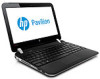
Fan Description Fan Spare part number 665000-001 NOTE: To properly ventilate the computer, allow at least 7.6 cm (3 in) of clearance on the left side of the computer. The computer uses an electric fan for ventilation. The fan is controlled by a temperature sensor and is designed to turn on automatically when high temperature conditions exist. These conditions are affected by high external temperatures, system power consumption, power management/battery conservation configurations, battery fast charging, and software requirements. Exhaust air is displaced through the ventilation grill located on the left side of the computer. Before removing the fan, follow these steps: 1. Shut down the computer. If you are unsure whether the computer is off or in Hibernation, turn the computer on, and then shut it down through the operating system. 2. Disconnect all external devices connected to the computer. 3. Disconnect the power from the computer by first unplugging the power cord from the AC outlet and then unplugging the AC adapter from the computer. 4. Remove the battery (see Battery on page 37), and then remove the following components: a. Service cover (see WLAN module on page 40) b. Keyboard (see Keyboard on page 48) c. Top cover (see Top cover on page 51) d. System board (see System board on page 54) Remove the fan: 1. Turn the system board upside down, with the front toward you. 2. Disconnect the fan cable (1) from the system board. 3. Remove the two Phillips PM2.0×4.6 screws (2) that secure the fan to the system board. 4. Remove the fan (3). Reverse this procedure to install the fan. Heat sink NOTE: The heat sink spare part kit includes replacement thermal material. Description Heat sink for use with the PCH chip with all computer models Spare part number 683843-001 58 Chapter 4 Removal and replacement procedures
-
 1
1 -
2
-
3
-
4
-
5
-
6
-
7
-
8
-
9
-
10
-
11
-
12
-
13
-
14
-
15
-
16
-
17
-
18
-
19
-
20
-
21
-
22
-
23
-
24
-
25
-
26
-
27
-
28
-
29
-
30
-
31
-
32
-
33
-
34
-
35
-
36
-
37
-
38
-
39
-
40
-
41
-
42
-
43
-
44
-
45
-
46
-
47
-
48
-
49
-
50
-
51
-
52
-
53
-
54
-
55
-
56
-
57
-
58
-
59
-
60
-
 61
61 -
 62
62 -
 63
63 -
 64
64 -
 65
65 -
 66
66 -
 67
67 -
 68
68 -
 69
69 -
 70
70 -
 71
71 -
72
-
73
-
74
-
75
-
76
-
77
-
78
-
79
-
80
-
81
-
82
-
83
-
84
-
85
-
86
-
87
-
88
-
89
-
90
-
91
-
92
-
93
-
94
-
95
-
96
-
97
-
98
 |
 |